Device for controlling vehicle drive apparatus

A driving device and control device technology, which is applied in transmission device control, road vehicle drive control system, control device, etc., can solve the problems of large inertia moment of rotating parts, etc., and achieve the goal of suppressing heat generation, improving durability, and improving durability Effect

Active Publication Date: 2016-09-28
AISIN AW CO LTD
View PDF6 Cites 2 Cited by
  • Summary
  • Abstract
  • Description
  • Claims
  • Application Information

AI Technical Summary

Problems solved by technology

[0004] However, as in Patent Document 1, if the specific engagement device is maintained in the direct-connected engaged state, the internal combustion engine and the rotating electrical machine rotate integrally, and the moment of inertia of the rotating member rotating integrally with the rotating electrical machine increases.
Therefore, there is a limit to shortening the period during which the rotation speed difference of the engagement device on the engagement side of the transmission is reduced by reducing the rotation speed of the rotary electric machine during the upshift control.

Method used


Image

  • Device for controlling vehicle drive apparatus
  • Device for controlling vehicle drive apparatus
  • Device for controlling vehicle drive apparatus

Examples


Embodiment Construction

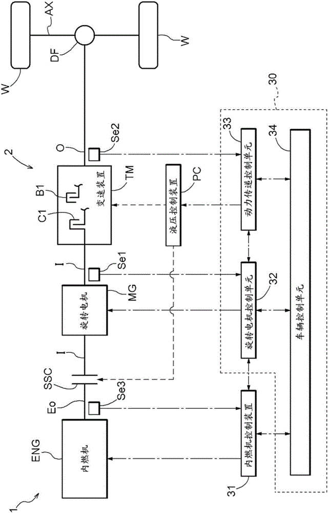
[0037] Embodiments of the control device 30 (hereinafter simply referred to as the control device 30 ) of the vehicle drive device 1 according to the present invention will be described with reference to the drawings. figure 1 It is a schematic diagram showing a schematic configuration of the vehicle drive device 1 and the control device 30 according to the present embodiment. In the figure, a solid line indicates a drive force transmission path, a dotted line indicates a hydraulic oil supply path, and a dotted line indicates a signal transmission path.

[0038]In the vehicle drive device 1 , a specific engagement device SSC, a rotary electric machine MG, and a transmission device TM are provided in order from the internal combustion engine ENG side on a power transmission path 2 connecting the internal combustion engine ENG to the wheels W. The specific engagement device SSC is in a selectively coupled state or a disengaged state between the internal combustion engine ENG and...


PUM


Abstract

A need exists for a control device that would allow the rotational speed of a rotating electric motor to be reduced and the period of a lower rotational speed difference for the engagement-side engaging device of a transmission to be shortened during on-upshift control. A control apparatus for a vehicle drive apparatus wherein a specific engagement device (SSC) is controlled to be in a state of sliding engagement, and the rotational speed of a rotating electric motor (MG) is reduced relative to the rotational speed of an internal combustion engine (ENG) when the rotational speed difference (DELTA W1) of the engagement-side engaging device is reduced during on-upshift control.

Description

technical field [0001] The present invention relates to a control device for a vehicle drive device which includes a specific engagement device, a rotary electric machine, and a transmission device in order from the internal combustion engine side on a power transmission path connecting an internal combustion engine and wheels. Background technique [0002] Regarding such a control device as described above, for example, a technique described in Patent Document 1 below is known. In the technique described in Patent Document 1, the upshift control (referred to as upshift control) is performed from the state in which the torque in the forward acceleration direction is being transmitted to the wheels until the specific engagement device is maintained in the directly coupled engagement state. ). [0003] Patent Document 1: Japanese Patent Application Laid-Open No. 9-331602 [0004] However, as in Patent Document 1, if the specific engagement device is maintained in the directl...

Claims


Application Information

Patent Timeline
Patent Type & Authority Applications(China)
IPC IPC(8): B60W10/02B60K6/48B60K6/547B60W10/06B60W10/08B60W10/11B60W20/00B60L50/16
CPCB60K6/48B60K6/547B60W10/06B60W10/08B60W10/11B60W30/19B60K2006/4825B60L15/2054B60L2240/12B60L2240/421B60L2240/423B60L2240/441B60L2240/443B60L2240/486B60L2240/507F16H61/0204F16H63/502B60L2210/40B60W10/115B60W20/30B60L50/16Y10S903/93B60W20/15Y02T10/62Y02T10/64Y02T10/7072Y02T10/72Y02T10/70B60W2556/00B60W10/02B60W10/04B60W10/10B60W20/00B60K6/36B60W2510/0638B60W2510/1005B60W2710/021B60W2710/025B60W2710/027B60W2710/0644B60W2710/081B60W2710/083B60W2710/1005B60W2710/105B60Y2200/92B60Y2300/19B60Y2400/72
Inventor 田岛阳一津田耕平
Owner AISIN AW CO LTD
Why Eureka
Try Eureka