
Reliably connected patch board assembly
A plug-in strip and component technology, which is applied to the parts, connections, and contact parts of the connecting device, can solve the problem of unsatisfactory use of the plug-in strip, and achieve the effect of simple structure, good electrical conductivity, and flexible movement
- Summary
- Abstract
- Description
- Claims
- Application Information
AI Technical Summary
Problems solved by technology
Method used
Image

Examples
Embodiment Construction
[0041] It should be noted that, in the case of no conflict, the embodiments in the present application and the features in the embodiments can be combined with each other; the present invention will be described in detail below with reference to the accompanying drawings and in combination with the embodiments.
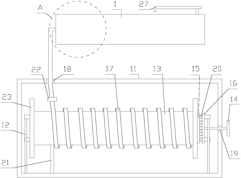
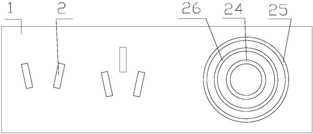
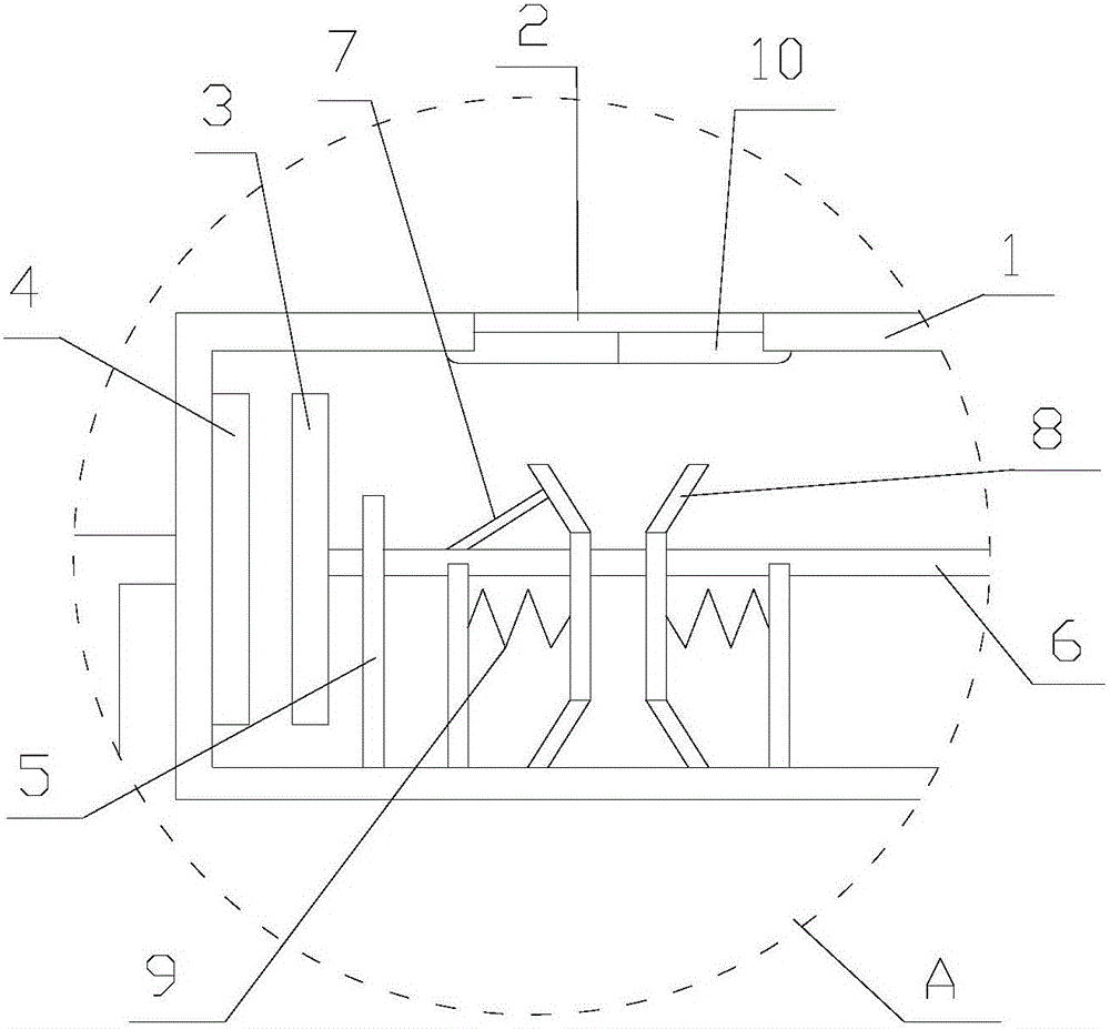
[0042] refer to figure 1 , 2 , 3:
[0043] A reliable plug-in assembly proposed by the present invention includes a housing 1, a switch unit, a plurality of conductive units, a box body 11, a mounting frame 12, a support plate 13 arranged in a ring, a handle 14, and a third conductor 15 , the fourth electrical conductor 16 , the first wire 17 , the second wire, a plurality of steel balls 20 , an elastic member 21 , a threading ring 22 , two flanges 23 , and a cover plate 27 .
[0044] The casing 1 is provided with a plurality of sockets 2 , and the casing 1 is provided with a receiving cavity.
[0045] The switch unit is placed in the accommodating cavity, and the ...
PUM
 Abstract
Description
Claims
Application Information