

Fire and explosion protection structure installed on cable intermediate head, and use method thereof
A technology of cable intermediate joints and explosion-proof structures, which is applied in the direction of cable joints, equipment for connecting/terminating cables, etc., can solve the problems of poor durability and low manufacturing cost, and solve the problems of poor durability and low manufacturing cost , high-strength effect
- Summary
- Abstract
- Description
- Claims
- Application Information
AI Technical Summary
Problems solved by technology
Method used
Image

Examples
Embodiment Construction
[0064] In order to facilitate the understanding of the technical content of the present invention, the technical solutions thereof will be further described below in conjunction with the accompanying drawings.
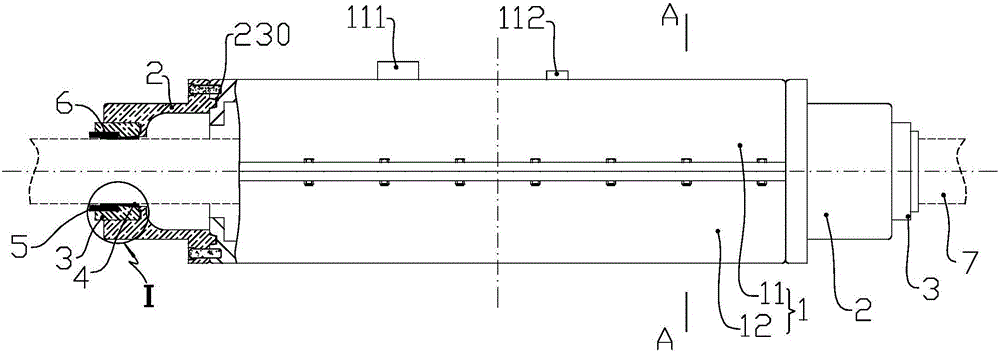
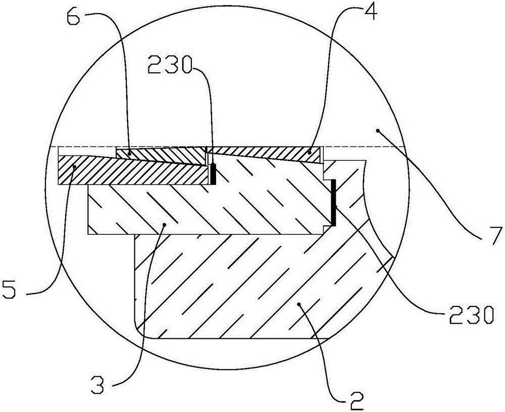
[0065] Such as figure 1 A fire-proof and explosion-proof structure installed at the middle joint of the cable is shown, including an outer box body 1 formed by fastening the upper half outer box 11 and the lower half outer box 12, and the assembly end connected to the left and right ports of the outer box body 1 The cover 2 and the primary sealing end cover 3 and inner sealing ring 4 arranged on the assembly end cover 2 .
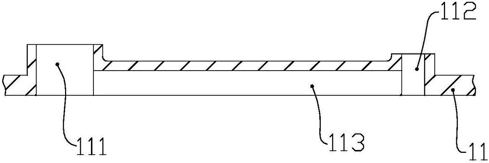
[0066] Such as figure 1 , Figure 4 As shown, corresponding mold grooves are provided on the upper half outer box 11 and the lower half outer box 12, and axially extending flanges 10 are respectively arranged on both sides of the transverse ports of the mold grooves. The groove here is as Figure 4 The settings shown are semicircular. On the lo...
PUM
 Abstract
Description
Claims
Application Information