
Binding machine for office supply bills and documents
A technology of office supplies and binding machines, which is applied in the direction of binding, etc., can solve the problems of shortening and easy damage of the pressure head module, and achieve the effects of reduced damage rate, good assembly and maintenance technology, and reduced personnel participation
- Summary
- Abstract
- Description
- Claims
- Application Information
AI Technical Summary
Problems solved by technology
Method used
Image

Examples
Embodiment Construction
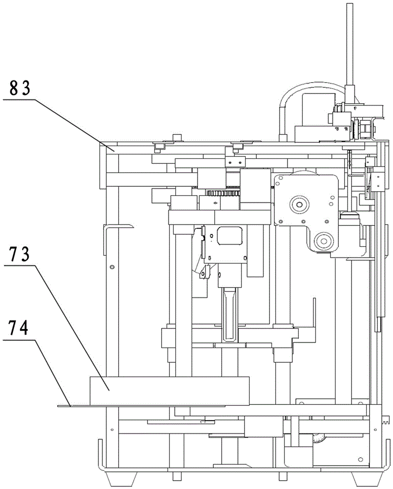
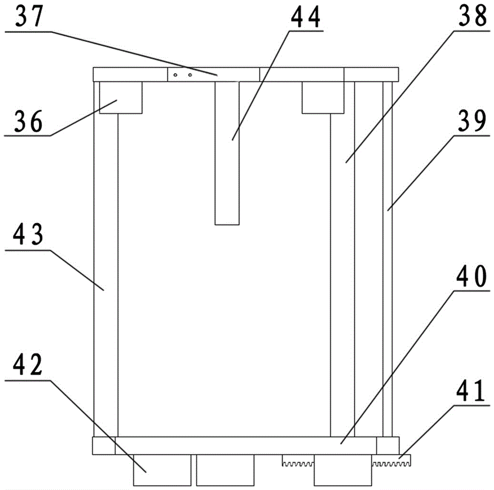
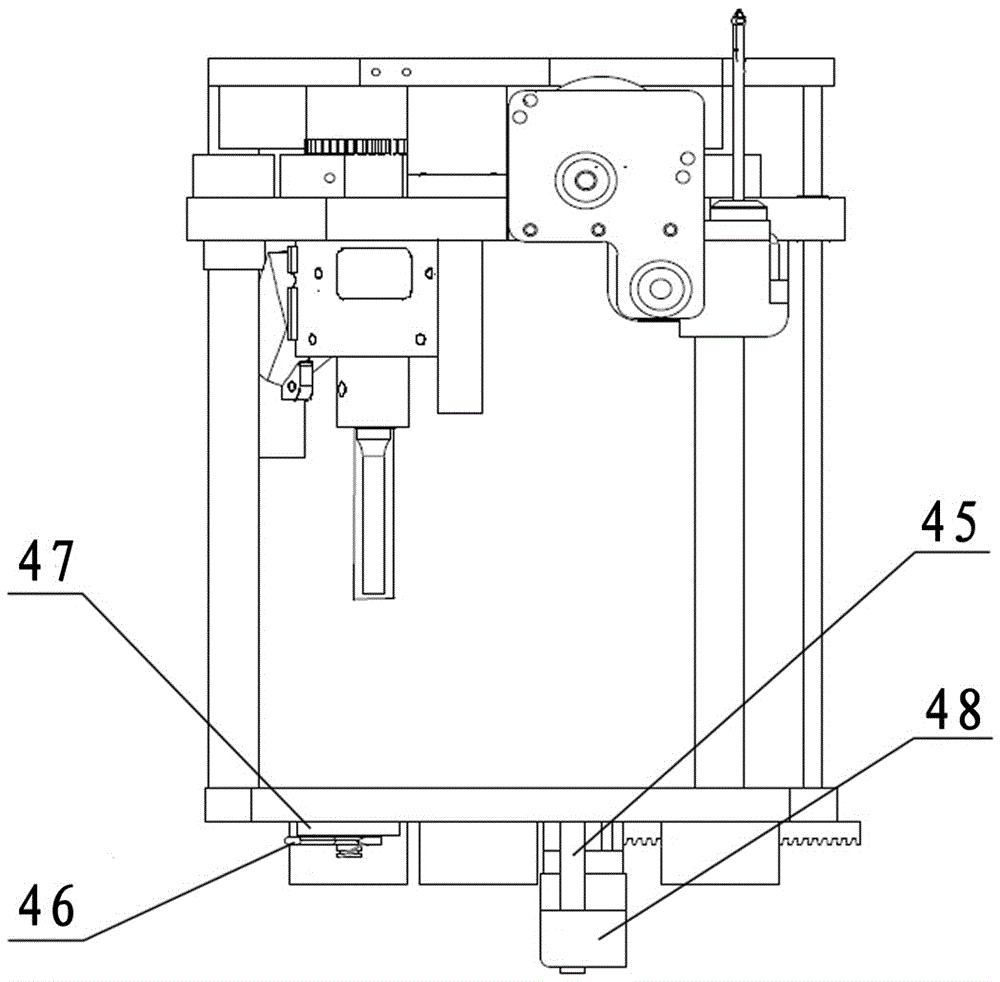
[0037] Such as figure 1 , figure 2 , image 3 As shown, the binding machine of the present invention is composed of an upper movable plate 37, a lower movable plate 40 and a first guide rod 38, a second guide rod 39 and a third guide rod 43 arranged between the upper movable plate 37 and the lower movable plate 40 make up a rectangular moving frame ( figure 2 ). On the upper moving plate 37, the upper sliding sleeve 36 and the fourth guide rod 44 extending downward are connected, and on the lower moving plate 40, the lower sliding sleeve 42 and the horizontal rack 41 are connected. Mobile frame is arranged in frame 83 (frame, also claims complete machine frame) ( figure 1 ), on the moving frame there are upper pressure riveting ironing head module, punching module, conductive rubber module and lower pressure riveting ironing head module ( image 3 ), the frame 83 is provided with working mechanisms such as a working panel 74, a binding tube in-position detection module,...
PUM
 Abstract
Description
Claims
Application Information