Uniform gas distribution device for high-pressure gas

A gas uniform distribution and distribution device technology, applied in the direction of branch pipelines, pipes, pipes/pipe joints/fittings, etc., can solve the problems of gas volume loss, low utilization rate of high-pressure gas, etc., and achieve stable operation, low cost, and device design reasonable effect

Active Publication Date: 2016-11-16
SHAOXING MIAOHUI ENERGY TECH CO LTD
View PDF6 Cites 2 Cited by
  • Summary
  • Abstract
  • Description
  • Claims
  • Application Information

AI Technical Summary

Problems solved by technology

Due to the limitation of the equipment used by the device itself, the gas flowing through is often concentrated, resulting in low utilization rate of high-pr

Method used


Image

  • Uniform gas distribution device for high-pressure gas
  • Uniform gas distribution device for high-pressure gas

Examples


Example Embodiment

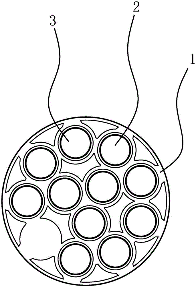
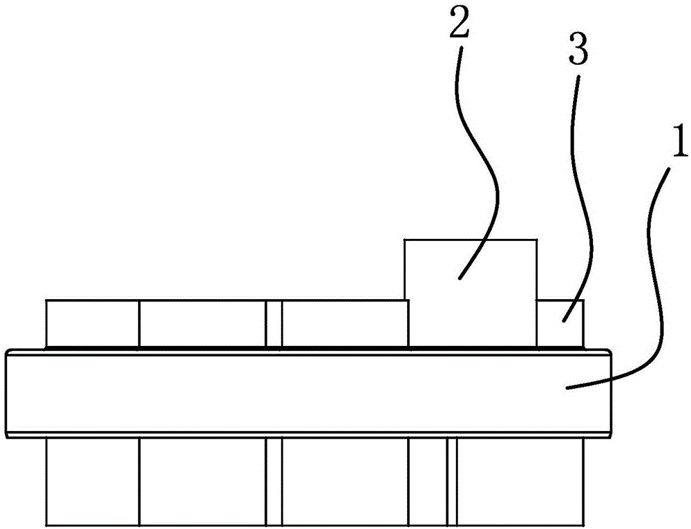
[0022] Such as figure 1 As shown, the gas uniform distribution device for high-pressure gas includes a disc-shaped body 1. The body 1 has an inlet pipe 2 and a plurality of distribution pipes 3, the middle of the inlet pipe 2 and the distribution pipe 3 It is connected to the body 1 and both ends of the intake pipe 2 and the distribution pipe 3 extend out of the main body 1. The length of the intake pipe 2 is greater than the length of the distribution pipe 3, and one end of the intake pipe 2 and the distribution pipe 3 The other end of the intake pipe 2 extends out of the distribution pipe 3 and is used to connect with a high-pressure gas source. The sides of the intake pipe 2 and the distribution pipe 3 have a ventilation structure that allows the gas in the intake pipe to enter the distribution pipe .

[0023] The ventilation structure includes a first through hole located on the side of the intake pipe 2 and a second through hole located on the distribution pipe 3. The two ad...


PUM


Abstract

The invention provides a uniform gas distribution device for high-pressure gas, and belongs to the technical field of machinery. The uniform gas distribution device solves the problem that in the prior art, applicability is poor. The uniform gas distribution device for the high-pressure gas comprises a disc-shaped body. The body is provided with a gas inlet pipe and multiple distribution pipes. The middle portion of the gas inlet pipe and the middle portions of the distribution pipes are connected to the body. The two ends of the gas inlet pipe and the two ends of each distribution pipe each extend out of the body. The length of the gas inlet pipe is larger than the length of the distribution pipes. One end of the gas inlet pipe is flush with one ends of the distribution pipes, and the other end of the gas inlet pipe extends out of the distribution pipes and is used for being connected with a high-pressure gas source. Ventilation structures capable of making gas in the gas inlet pipe enter the distribution pipes are arranged on the side portion of the gas inlet pipe and the side portions of the gas distribution pipes. The uniform gas distribution device for the high-pressure gas is high in applicability.

Description

technical field [0001] The invention belongs to the technical field of machinery and relates to a gas uniform distribution device for high-pressure gas. Background technique [0002] In the process of using high-pressure gas, it often involves the change of the pipe diameter of the pipeline for transporting high-pressure gas. Due to the limitation of the equipment used by the device itself, the gas flowing through is often concentrated, resulting in low utilization rate of high-pressure gas and unnecessary loss of gas volume. After retrieval, there is no design device suitable for high-pressure gas in the existing gas uniform distributor. In order to solve the deficiencies of the prior art, the present invention proposes a uniform gas distribution cavity device suitable for high-pressure gas. Contents of the invention [0003] The object of the present invention is to solve the above-mentioned problems in the prior art, and provide a gas uniform distribution device for h...

Claims


Application Information

Patent Timeline
IPC IPC(8): F16L41/03
CPCF16L41/03
Inventor 林欣然孙阳陆明伟周栋孙荣军李林魏本柱王建民
Owner SHAOXING MIAOHUI ENERGY TECH CO LTD
Why Eureka
Try Eureka