A high-efficiency dust and mist removal device with acoustic wave coupling swirl-race-swirl

A technology of demisting device and swirling flow, which is applied in the field of flue gas purification, can solve the problems of low removal efficiency, small pressure loss, and high efficiency of dust and mist removal, and achieve high dust and fog removal efficiency, low energy consumption, Good dust and fog removal effect

Active Publication Date: 2019-07-12
SHANGHAI JIAOTONG UNIV
View PDF2 Cites 0 Cited by
  • Summary
  • Abstract
  • Description
  • Claims
  • Application Information

AI Technical Summary

Problems solved by technology

[0005] The purpose of the present invention is to overcome the defects in the prior art and provide a dust removal and mist removal with high efficiency and small pressure loss, which can better realize the deep dust removal and removal of saturated wet flue gas containing a large number of liquid droplets after desulfurization. Acoustic coupling swirl-swirl high-efficiency dust and mist removal device with fog effect is used to solve the technical problems of low removal efficiency of the existing swirl plate dust removal and mist removal device

Method used


Image

  • A high-efficiency dust and mist removal device with acoustic wave coupling swirl-race-swirl
  • A high-efficiency dust and mist removal device with acoustic wave coupling swirl-race-swirl
  • A high-efficiency dust and mist removal device with acoustic wave coupling swirl-race-swirl

Examples


Embodiment 1

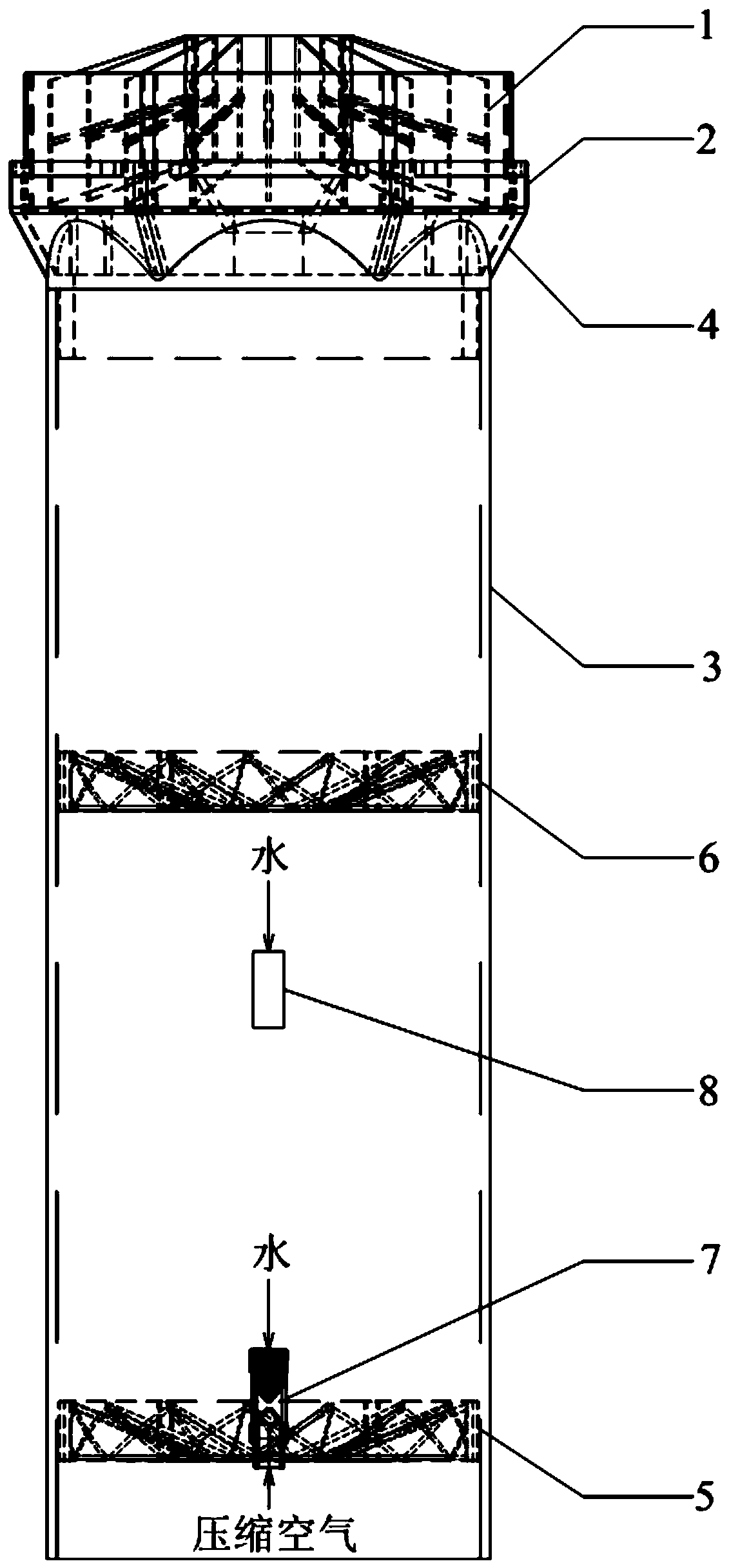
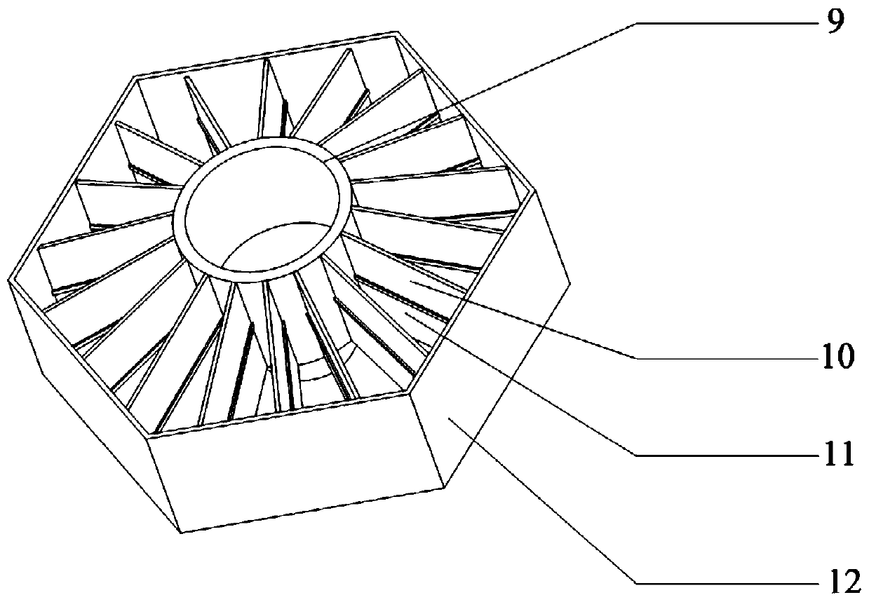
[0044] Such as figure 1 As shown in the figure, a sound-wave coupling cyclone-race-rotation high-efficiency dedusting and mist removal device is arranged above the spray layer in the desulfurization absorption tower, and includes multiple dust and mist removal units installed side by side. The dust removal and mist removal unit includes external The cylinder body, the first-stage centrifugal swirl plate 5 and the second-stage centrifugal swirl plate 6 arranged in parallel in the outer cylinder from bottom to top, and the racemic hydrophobic plate 1 obliquely arranged on the top of the outer cylinder, the first stage A sound wave generator 7 is arranged at the center of the centrifugal swirl plate 5 , and a flushing water injector 8 is arranged between the sound wave generator 7 and the second-stage centrifugal swirl plate 6 .

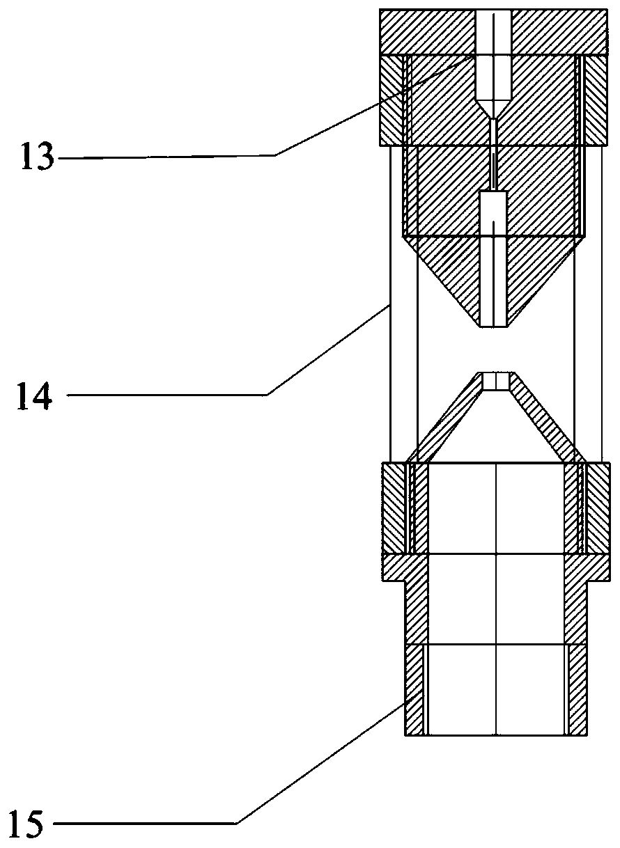
[0045] The acoustic wave generator 7 includes an airflow nozzle 15 whose bottom is fixedly connected to the first-stage centrifugal swirl plate 5 , a r...

Embodiment 2

[0054] In the present embodiment, the height of the acoustic wave generator 7 is 80 mm, and the diameter is 25 mm. The nozzle diameter of the air flow nozzle 15 is 5 mm, and the spray distance is 8 mm. The depth of the resonant cavity 13 is 20 mm. The overall height is 60mm.

[0055] All the other are with embodiment 1.

[0056] Using a test tower with an inner diameter of 700mm, the amount of flue gas used in the test is 2000m 3 / h, the flue gas temperature is 90°C, and the inlet droplet concentration is 250mg / Nm 3 , soot content is 75mg / Nm 3 . The measured demist efficiency is about 97%, the dust removal efficiency is 95%, and the total tower resistance is around 180Pa.

Embodiment 3

[0058] In the acoustic wave coupling swirling-descending high-efficiency dust and mist removal device of this embodiment, the ratio of the diameter of the acoustic wave generator 7 to the first-stage centrifugal swirl plate 5 is 1:20, and the nozzle of the airflow nozzle 15 in the acoustic wave generator 7 The ratio of the diameter to the spray distance is 0.2:1, the ratio of the outer diameter of the resonant cavity 13 to the spray distance is 2:1, the ratio of the depth of the resonant cavity 13 to the spray distance is 3:1, and the bottom of the resonant cavity 13 is provided with a flushing Water distribution port for continuous or intermittent addition of rinse water. In the working state, the injection volume of flushing water is 0.2m 3 / h.

[0059] The sound wave generator 7 adopts the jet power of compressed air or steam as the sound wave generation source, the distance between the air flow nozzle 15 and the resonant cavity 13 is 3mm, and in the working state, the flo...


PUM

PropertyMeasurementUnit
diameteraaaaaaaaaa
diameteraaaaaaaaaa
diameteraaaaaaaaaa

Abstract

The invention relates to a sound-wave-coupling rotational flow-rotation eliminating efficient dust removing and defogging device. The sound-wave-coupling rotational flow-rotation eliminating efficient dust removing and defogging device is arranged above a spraying layer in a desulfurization absorption tower and comprises a plurality of dust removing and defogging units which are parallelly mounted. Each dust removing and defogging unit comprises an outer cylinder, a primary centrifugal rotational-flow plate, a secondary centrifugal rotational-flow plate and a rotation-eliminating hydrophobic plate, wherein the primary centrifugal rotational-flow plate and the secondary centrifugal rotational-flow plate are sequentially parallelly arranged in the outer cylinder from bottom to top, the rotation-eliminating hydrophobic plate is obliquely arranged at the top of the outer cylinder, a sound wave generator is arranged at the center of the primary centrifugal rotation-flow plate, and a washing water sprayer is arranged between the sound wave generator and the secondary centrifugal rotation-flow plate. Compared with the prior art, the sound-wave-coupling rotational flow-rotation eliminating efficient dust removing and defogging device has the advantages that the device integrates the features of sound wave and rotational-flow centrifugal dust removing and defogging, and the device is simple and compact in overall structure, low in investment cost, good in operation stability, free of scaling and blocking risks, capable of achieving deep dust removing and defogging of saturated wet flue gas after desulfurization under low investment cost and operation cost, low in resistance loss and promising in application prospect.

Description

technical field [0001] The invention belongs to the technical field of flue gas purification, and relates to a dust and mist removal device, in particular to an acoustic wave coupling swirl-deseration high-efficiency dust and mist removal device. Background technique [0002] The ultra-low emission of flue gas from coal-fired power plants and large-scale industrial boilers in my country will gradually become popular. Now there are more and more large-scale towers, especially in recent years, a large number of flue gas desulfurization projects have been built. Generally, the diameter of flue gas wet desulfurization absorption towers is at least More than 4 meters. However, most of the large amount of flue gas emitted by wet flue gas desulfurization is intercepted by baffle plate demister before leaving the absorption tower. The droplet content at the outlet of conventional mechanical demister is 75mg / Nm 3 , causing a large number of droplets to escape, and making the dust co...

Claims


Application Information

Patent Timeline
Patent Type & Authority Patents(China)
IPC IPC(8): B01D45/16B01D45/08B01D51/08
CPCB01D45/08B01D45/16B01D51/08
Inventor 晏乃强瞿赞黄文君刘伟贾金平
Owner SHANGHAI JIAOTONG UNIV
Why Eureka
Try Eureka