
Electric power big data all-in-one machine
A big data, all-in-one technology, applied in electrical digital data processing, digital data processing components, digital processing power distribution, etc., can solve problems such as huge data scale, complex data sources, and variable data applications.
- Summary
- Abstract
- Description
- Claims
- Application Information
AI Technical Summary
Problems solved by technology
Method used
Image


Examples
Embodiment
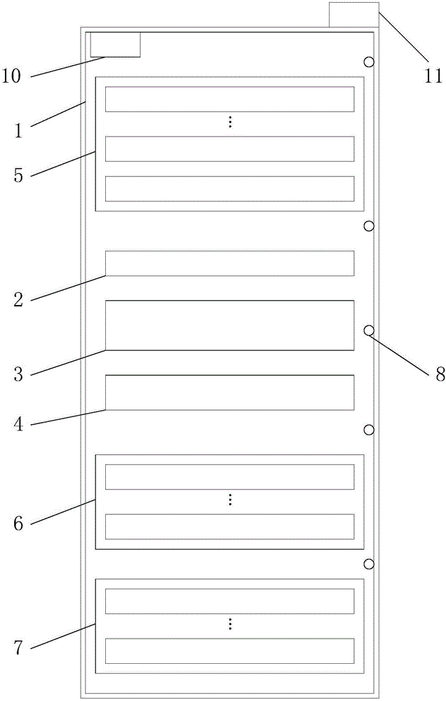
[0041] An embodiment of the present invention provides a power big data integrated machine, see figure 1 , the power big data all-in-one machine can include:
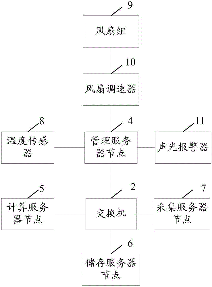
[0042] Cabinet 1, a switch 2 arranged in the cabinet 1, a cabinet power supply 3, a management server node 4, at least one computing server node 5, at least one storage server node 6, and at least one collection server node 7, see image 3 , the switch 2 is respectively connected to the management server node 4, the computing server node 5, the storage server node 6, and the acquisition server node 7, and the cabinet power supply 3 (not in the attached image 3 ) are respectively connected to the switch 2, the management server node 4, the computing server node 5, the storage server node 6, and the collection server node 7.
[0043] The switch 2 is used to implement data transmission between the management server node 4 , the computing server node 5 , the storage server node 6 , and the collection server node 7 .
[0...
PUM
 Abstract
Description
Claims
Application Information