Voltage sampling circuit

A technology of voltage sampling and sampling resistance, applied in the field of switching power supply, can solve problems such as affecting the accuracy of LED current control, and achieve the effect of reducing circuit volume and cost

Active Publication Date: 2017-02-08
JOULWATT TECH ZHANGJIAGANG INC LTD
View PDF5 Cites 7 Cited by
  • Summary
  • Abstract
  • Description
  • Claims
  • Application Information

AI Technical Summary

Problems solved by technology

Finally, in order to reduce the power loss of the control circuit, the general control circuit takes power from the drain of the power switch tube M01, so that the operating current of the control circuit will flow through the LED without passing through the sampling resistor, which will affect the control accuracy of the LED current.

Method used


Image

  • Voltage sampling circuit
  • Voltage sampling circuit
  • Voltage sampling circuit

Examples


Embodiment Construction

[0044] Some preferred embodiments of the present invention will be described in detail below with reference to the accompanying drawings, but the present invention is not limited thereto.

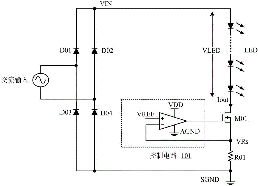
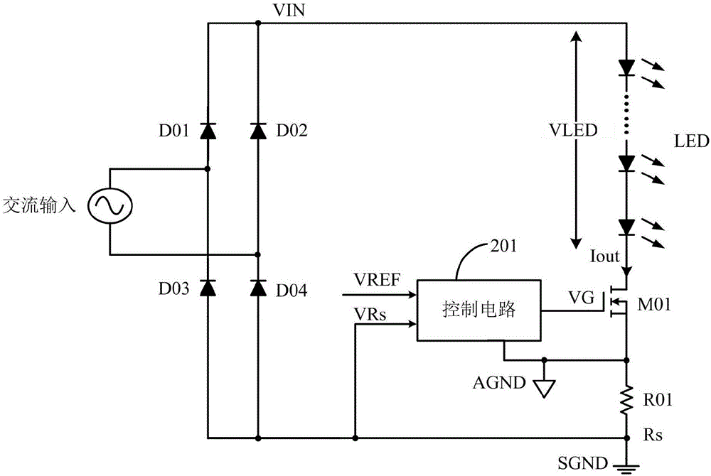
[0045] refer to figure 2 It is a schematic diagram of the LED driving circuit according to the present invention, the LED driving circuit is used to drive the LED load, and the external AC input voltage is rectified by the rectifier bridge (D01-D04) to output the pulsating DC voltage VIN to drive the LED load.

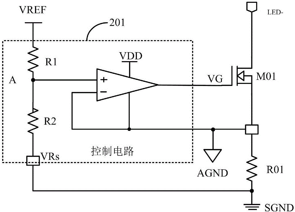
[0046] In the embodiment of the present invention, the LED driving circuit also includes a voltage sampling circuit, such as figure 2 As shown, the voltage sampling circuit includes a control circuit 201, a power switch tube M01 and a sampling resistor R01, and the power switch tube M01 and the sampling resistor R01 are sequentially connected in series with the LED load; the reference ground terminal AGND of the control circuit 201 is connected to The first terminal of the sampli...


PUM


Abstract

The invention discloses a voltage sampling circuit. The reference ground end of a control circuit and the ground end of a system are connected by a sampling resistor, the source of a power switching tube is connected with the reference ground end of the control circuit, and the voltage detection pin of the sampling voltage is connected with the ground end of the system. When an LED current flows through the sampling resistor, the control circuit obtains a negative sampling voltage, and the control circuit performs conversion to get the absolute value information of a sampling voltage signal so as to control the LED current. By using the control scheme of the invention, the following beneficial effects are achieved: the gate and source voltages of the power switching tube are not affected by the voltage of the sampling resistor, and the phenomenon that the driving voltage is low is avoided; no special ESD treatment is need for the source of the power switching tube, and the size and cost are reduced; and the working current of the control circuit flows through the sampling resistor when the control circuit takes electricity from the drain of the power switching tube, and the control precision of output current is high.

Description

technical field [0001] The invention relates to the field of switching power supplies, more specifically, to a voltage sampling circuit and an LED driving circuit. Background technique [0002] The schematic diagram of a traditional LED drive circuit is shown in figure 1 as shown, figure 1 Shown in is to control the driving current of the LED in a linear manner, and the linear regulator includes a power switch tube M01, a control circuit 101 and a sampling resistor R01. The AC input voltage is rectified by the rectifier bridge (D01-D04) to obtain a pulsating DC voltage VIN of twice the power frequency. When the DC voltage VIN is greater than the voltage drop (VLED) of the LED load, the power switch connected in series with the LED load The tube M01 starts conducting, and the ground of the control circuit 101 (such as figure 1 AGND) and system ground (such as figure 1 SGND) is directly connected, the current of the LED flows through the sampling resistor R01, the sampling...

Claims


Application Information

Patent Timeline
Patent Type & Authority Applications(China)
IPC IPC(8): H05B33/08H05B44/00
CPCH05B45/40H05B45/50Y02B20/30
Inventor 查振旭黄必亮任远程周逊伟
Owner JOULWATT TECH ZHANGJIAGANG INC LTD
Why Eureka
Try Eureka