Automatic imbalance point tracking apparatus for dynamic wheel balancing machine

A dynamic balancing machine, automatic tracking technology, applied in static/dynamic balance testing, measuring device, testing of machine/structural components, etc. Complex problems, etc., to achieve the effect of simple structure, complex structure and few parts

Active Publication Date: 2017-02-15
哈尔滨朗格科技开发有限公司
View PDF7 Cites 3 Cited by
  • Summary
  • Abstract
  • Description
  • Claims
  • Application Information

AI Technical Summary

Problems solved by technology

[0004] In order to solve the problem that the indication method of the wheel unbalance point in the existing ALUS mode is complicated, the operation is difficult

Method used


Image

  • Automatic imbalance point tracking apparatus for dynamic wheel balancing machine
  • Automatic imbalance point tracking apparatus for dynamic wheel balancing machine
  • Automatic imbalance point tracking apparatus for dynamic wheel balancing machine

Examples


Embodiment 1

[0030] Example 1: Combine below Figure 1 to Figure 4 This embodiment will be described in detail.

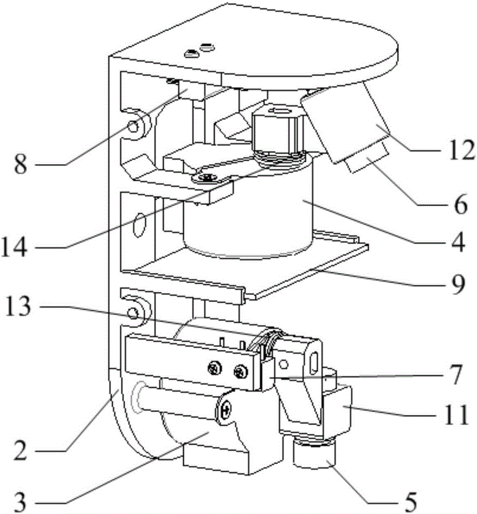
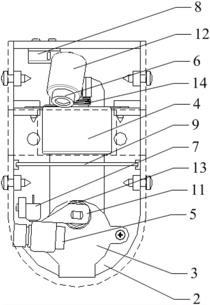
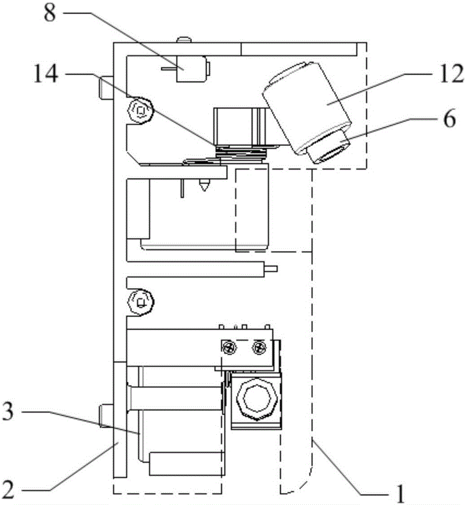
[0031] The automatic tracking device for unbalanced points of the wheel dynamic balancing machine in this embodiment includes a shield 1, a bracket 2, a first stepping motor 3, a second stepping motor 4, a first laser 5, and a second laser 6. , The first zero-point positioning body 7, the second zero-point positioning body 8, the driver 9 and the processor;

[0032] One side of the shield 1 is open, and the bracket 2 is fixedly arranged on the opening side of the shield 1, forming the housing of the device, the first stepping motor 3, the second stepping motor 4, the first laser 5, and the second laser 6. The first zero-point positioning body 7, the second zero-point positioning body 8, the driver 9 and the processor are all located inside the housing;

[0033] The first stepping motor 3 and the second stepping motor 4 are both rotating motors, the first stepping motor 3 and the seco...

Embodiment 2

[0042] Embodiment 2: The following combination Figure 1 to Figure 3 This embodiment will be described in detail. This embodiment further restricts the automatic tracking device for unbalanced points on the wheel dynamic balancing machine described in the first embodiment.

[0043] In the automatic tracking device for unbalance points on the wheel dynamic balancing machine in this embodiment, the first laser 5 is fixedly arranged on the output shaft of the first stepping motor 3 through the first fixing base 11, and the second laser 6 passes through the The two fixing seats 12 are fixedly arranged on the output shaft of the second stepping motor 4.

[0044] In this embodiment, the laser is fixed on the output shaft of the stepping motor through the fixing seat, and the fixing seat can also play a role in protecting the laser during the process of returning the position of the output shaft of the stepping motor to zero.

Embodiment 3

[0045] Embodiment 3: Combine below Figure 1 to Figure 3 This embodiment will be described in detail. This embodiment further restricts the automatic tracking device for unbalanced points of the wheel dynamic balancing machine described in the second embodiment.

[0046] The automatic tracking device for imbalance points on the wheel dynamic balancing machine described in this embodiment further includes a first coil spring 13 and a second coil spring 14. The first coil spring 13 and the second coil spring 14 are used to reduce the The backlash between the output shaft of a stepping motor 3 and the output shaft of the second stepping motor 4.

[0047] In this embodiment, both ends of the first coil spring are respectively fixedly connected to the bracket and the first fixing seat, and both ends of the second coil spring are respectively fixedly connected to the bracket and the second fixing seat. The two coil springs respectively make the output angles of the output shaft of the ...


PUM


Abstract

The invention, which belongs to the dynamic balancing machine field, provides an automatic imbalance point tracking apparatus for a dynamic wheel balancing machine. With the apparatus, problems of tedious indication way steps and high operation difficulty of the wheel imbalance point in an existing ALUS mode or complicated structure of the employed indication apparatus can be solved. An output shaft of a first stepping motor is perpendicular to an output shaft of a second stepping motor; a first laser and a second laser are arranged on the output shaft of the first stepping motor and the output shaft of the second stepping motor respectively; and the output shaft of the first stepping motor and the output shaft of the second stepping motor are parallel to emergent light of the first laser and emergent light of the second laser respectively. A first zero-point positioning body and a second zero-point positioning body are used for zero-point positioning of the output shafts of the first stepping motor and the second stepping motor. A grating signal output terminal and a correction plane position data output terminal of a dynamic balancing machine are connected with a grating signal output terminal and a correction plane position data output terminal of a processor; and a driver drives the first stepping motor and the second stepping motor respectively by a first control signal and a second control signal that are sent out by the processor. According to the invention, the provided apparatus are used for automatic imbalance point tracking of a dynamic wheel balancing machine.

Description

Technical field [0001] The invention relates to an automatic tracking device for unbalanced points on a wheel dynamic balancing machine, belonging to the field of dynamic balancing machines. Background technique [0002] After the wheel dynamic balancer measures the dynamic unbalance of the wheel, it is necessary to indicate the unbalance point on the wheel, that is, indicate the position of the unbalance point on the two correction surfaces, so as to correct the unbalance. Existing wheel dynamic balancing machines usually have two balancing modes, one is DYN mode, in this mode, users can only select the two preset correction surfaces in the dynamic balancing machine; the other is ALUS mode, in which In the mode, the user can freely select two calibration surfaces. [0003] Therefore, after the wheel dynamic balancer in the ALUS mode measures the dynamic unbalance of the wheel, the indication of the unbalance point on the wheel includes both the position of the correction surface ...

Claims


Application Information

Patent Timeline
IPC IPC(8): G01M1/26
CPCG01M1/26
Inventor 王成贵张云奎王忠磊吴启刘万峰
Owner 哈尔滨朗格科技开发有限公司
Why Eureka
Try Eureka