High-pressure gas-liquid separation control device and control method thereof

A control device and liquid separation technology, applied in electrical program control, program control in sequence/logic controllers, measurement devices, etc., can solve problems such as insufficient separation capacity of low-pressure separators, and achieve easy maintenance and replacement. Effect

Active Publication Date: 2017-03-22
BC P INC CHINA NAT PETROLEUM CORP +1
View PDF4 Cites 6 Cited by
  • Summary
  • Abstract
  • Description
  • Claims
  • Application Information

AI Technical Summary

Problems solved by technology

[0007] The purpose of the present invention is to overcome the above-mentioned problems in the prior art, provide a high-pressure gas-liquid separation control device and method, and solve the pro

Method used


Image

  • High-pressure gas-liquid separation control device and control method thereof
  • High-pressure gas-liquid separation control device and control method thereof
  • High-pressure gas-liquid separation control device and control method thereof

Examples


Embodiment 1

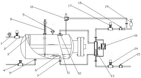
[0048] This embodiment provides a high-pressure gas-liquid separation control device, such as figure 1 As shown, it includes a separation tank, the separation tank is connected with a liquid inlet line, and the separation tank is provided with a liquid outlet 7, an air outlet 12 and a sewage outlet 5. The separation tank can be a horizontal or vertical separation tank. In this embodiment, A horizontal separation tank is used, and its gas phase processing capacity is 3 to 5 times that of a vertical separator. The separation tank is also equipped with a magnetic flap level gauge 8 and a temperature and pressure transmitter 9 for real-time detection and separation. device working condition.

[0049] A pressure transmitter 1 and a liquid inlet electric control valve 2 are provided on the liquid inlet line, and a rectifying plate 3 is provided at the liquid inlet of the separation tank connected to the liquid inlet line. The sewage outlet 5 is connected to the sewage pipeline, and...

Embodiment 2

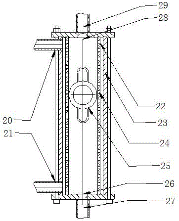
[0064] In order to realize that when the gas-liquid ratio changes greatly, the liquid outlet can only output liquid, and the gas outlet can only output gas. In this embodiment, the coaxial float valve 13 and the balance valve 16 are installed outside the separation tank, which is convenient for replacement and maintenance. The air inlet of the coaxial float valve 13 is level with the highest liquid level inside the separator, and the liquid inlet of the coaxial float valve 13 is lower than the lowest liquid level inside the separator by a float height.

[0065] Such as image 3 As shown, in this embodiment, the coaxial float valve 13 adopts an interlocking float, and the coaxial float valve 13 includes a coaxial float valve shell 23 and a coaxial float valve inner shell 22 coaxially set, and the upper part of the coaxial float valve shell 23 The coaxial float valve inlet 20 and the coaxial float valve liquid inlet 21 are respectively arranged on the bottom and the coaxial flo...

Embodiment 3

[0086] Based on the structures in the above two embodiments, in the present embodiment, the liquid outlet 7 at the bottom of the separation tank is provided with a liquid level stabilizer 6, such as Figure 5 As shown, the liquid level stabilizer 6 is a column structure with one end closed horizontally, the bottom side of the column is evenly distributed with liquid inlet holes, and the outlet at the end of the column communicates with the liquid outlet 7 . The gas outlet 12 on the top of the separation tank is provided with a mist catcher 11 . The separator is also connected to a safety valve 10 through a pipeline, and the exhaust pipe connected to the coaxial float valve 13 is communicated with the safety valve 10 through a branch line.

[0087] The liquid outlet 7 of the separation tank can form a concave vortex when discharging liquid, and suck the air flow. The larger the concave vortex, the stronger the gas phase suction volume, and the more serious the gas cone phenome...


PUM


Abstract

The invention relates to a high-pressure gas-liquid separation control device and a control method thereof. The high-pressure gas-liquid separation control device comprises a horizontal or vertical separating tank and a PLC (programmable logic controller), wherein a liquid outlet and a gas outlet of the separating tank are connected with a float valve; the coaxial float valve communicates with a balance valve; the upper part of the coaxial float valve is connected with a gas discharge pipeline, and the bottom is connected with a liquid discharge pipeline; the liquid discharge pipeline and gas discharge pipeline are respectively provided with an electric control regulating valve and a flowmeter; the liquid outlet of the separating tank is provided with a liquid level stabilizer; the liquid inlet of the separating tank is provided with an electric control regulating valve; the separating tank is also provided with a rectifying plate and a magnetic turning plate liquidometer; the PLC respectively monitors the separator working pressure, gas flowmeter water content and liquid flowmeter race condition; and the PLC controls the electric control regulating valves at the liquid inlet, the liquid outlet and the gas outlet. The high-pressure gas-liquid separation control device and control method thereof solve the problem of liquid discharge at the gas outlet and gas discharge at the liquid outlet due to the insufficient separating capacity of the low-pressure separator and manual control of the high-pressure separator.

Description

technical field [0001] The invention belongs to the field of gas-liquid separation, and in particular relates to a high-pressure gas-liquid separation control device and a control method thereof. Background technique [0002] Gas well acidizing flowback fluid treatment is an essential process in oilfield acidizing operations, and the gas-liquid separator is the main separation equipment in the operation process. At present, due to improper design or operation control methods, the gas-liquid separator does not meet the needs of flowback liquid treatment. In the process of operation, depending on the experience and observation of workers, the switch of the outlet control valve is manually adjusted to exhaust and discharge liquid, which often causes liquid to flow out of the gas outlet and gas to flow out of the liquid outlet. Especially when the inlet pressure and flow rate change, due to the way of manually switching the valve, a large amount of liquid is carried at the gas ...

Claims


Application Information

Patent Timeline
IPC IPC(8): C02F1/20E21B41/00G05B19/05G01D21/02C02F103/10
CPCC02F1/20C02F2103/10C02F2209/005C02F2209/02C02F2209/03C02F2209/38C02F2209/40C02F2209/42E21B41/005E21B41/0092G01D21/02G05B19/05
Inventor 孙虎王祖文邓继学刘建平韩静静侯光东景志明张冕龙庆费节高王松吕希祥
Owner BC P INC CHINA NAT PETROLEUM CORP
Why Eureka
Try Eureka