Fixed point mechanism

A component and shaft structure technology, applied in the field of fixed point mechanism

Active Publication Date: 2017-04-26
SHANGHAI MICROPORT MEDBOT (GRP) CO LTD
View PDF7 Cites 15 Cited by
  • Summary
  • Abstract
  • Description
  • Claims
  • Application Information

AI Technical Summary

Problems solved by technology

[0006] The purpose of the present invention is to provide a fixed point mechanism to solve the problem in the prior art that the fixed point formed by the double parallelogram fixed point mechanism has only one degree of freedom

Method used


Image

  • Fixed point mechanism
  • Fixed point mechanism
  • Fixed point mechanism

Examples


Embodiment 1

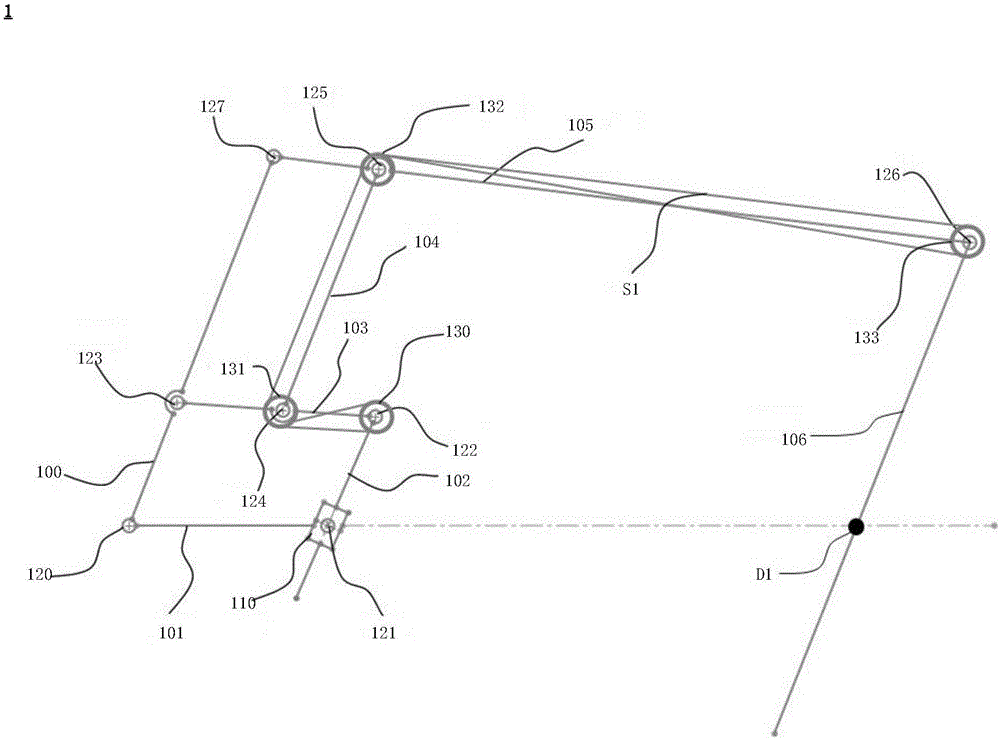
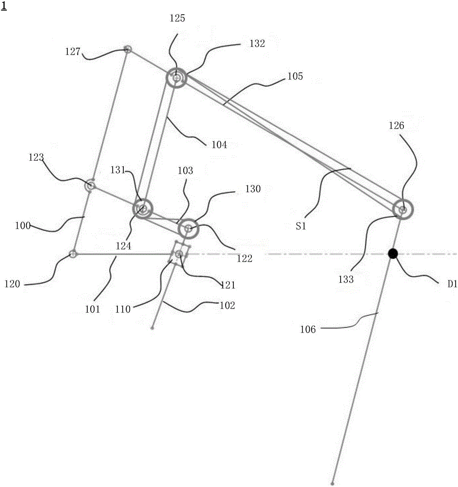
[0105] Please refer to figure 1 , which is a schematic diagram of the principle of the fixed point mechanism in Embodiment 1 of the present invention. Such as figure 1 As shown, the fixed point mechanism 1 includes: a driving component, a driven component and a transmission component. Specifically, the active component includes: a first link member 100, a second link member 101, a third link member 102, a fourth link member 103 and a slider device 110, wherein the first link The first end (the lower end here) of the member 100 forms a rotational connection with the first end (the proximal end here) of the second link member 101 through the first rotating shaft structure 120, and the second link member 101 The second end (the distal end here) is rotationally connected with the slider device 110 through the second rotating shaft structure 121, the third link member 102 forms a sliding connection with the slider device 110, and the first The three link members 102 pass through...

Embodiment 2

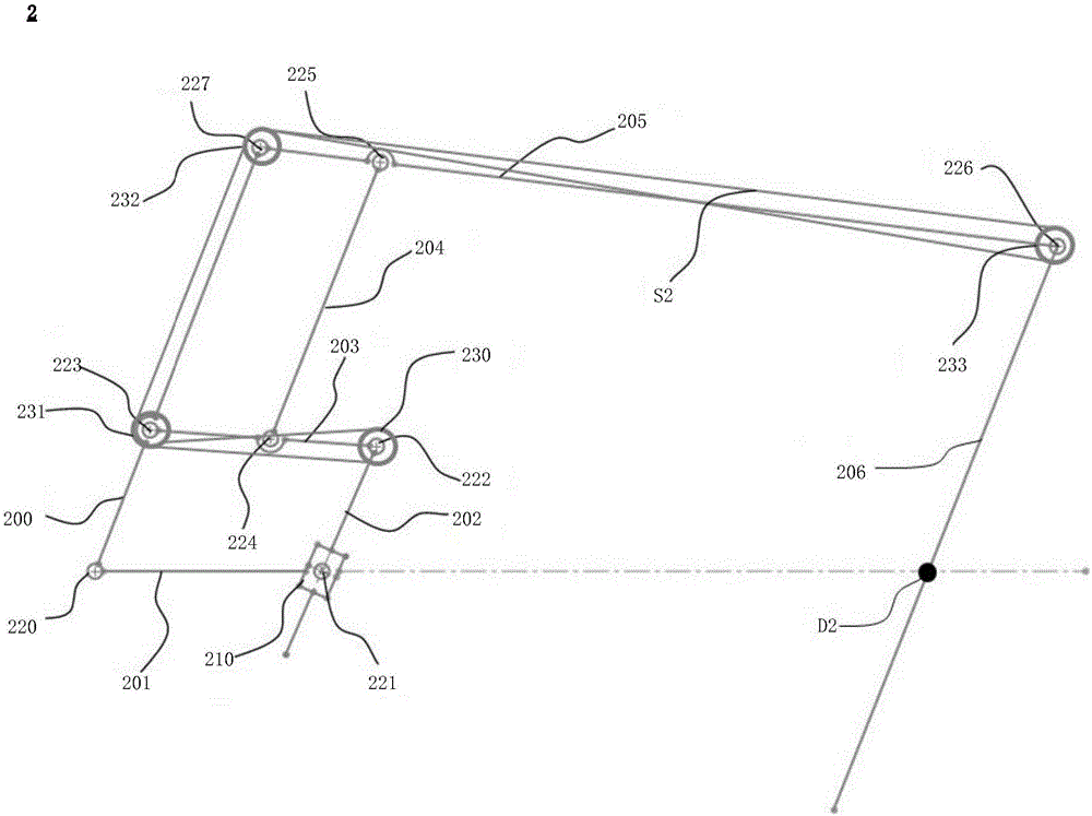
[0119] Please refer to image 3 , which is a schematic diagram of the principle of the fixed point mechanism in Embodiment 2 of the present invention. Such as image 3 As shown, the fixed point mechanism 2 includes: a driving component, a driven component and a transmission component. Specifically, the active component includes: a first link member 200, a second link member 201, a third link member 202, a fourth link member 203 and a slider device 210, wherein the first link The first end (the lower end here) of the member 200 forms a rotational connection with the first end (the proximal end here) of the second link member 201 through the first rotating shaft structure 220, and the second link member 201 The second end (the distal end here) forms a rotational connection with the slider device 210 through the second shaft structure 221, the third link member 202 forms a sliding connection with the slider device 210, and the third The connecting rod member 202 passes through...

Embodiment 3

[0132] Please refer to Figure 5 , which is a schematic diagram of the principle of the fixed point mechanism in Embodiment 3 of the present invention. Such as Figure 5 As shown, the fixed point mechanism 3 includes: a driving component, a driven component and a transmission component. Specifically, the active component includes: a first link member 300, a second link member 301, a third link member 302, a fourth link member 303 and a slider device 310, wherein the first link The first end (the lower end here) of the member 300 forms a rotational connection with the first end (the proximal end here) of the second link member 301 through the first rotating shaft structure 320, and the second link member 301 The second end (the distal end here) forms a rotational connection with the slider device 310 through the second rotating shaft structure 321, the third link member 302 forms a sliding connection with the slider device 310, and the The third connecting rod member 302 pas...


PUM


Abstract

The invention provides a fixed point mechanism. In the fixed point mechanism, when a driving torque is acted on a first connecting rod component or a slide block device, the fixed point mechanism can realize a rotating motion around a fixed point; when the driving torque is acted on a fourth connecting rod component or a sixth connecting rod component, the fixed point mechanism can realize an extending motion corresponding to the fixed point; and when the driving torque is acted on the first connecting rod component or the slide block device, the other driving torque is acted on the fourth connecting rod component or the sixth connecting rod component, the fixed point mechanism can realize the rotating motion around the fixed point and the extending motion corresponding to the fixed point. That is, the fixed point mechanism has double degrees of freedom of the rotating motion around the fixed point and the extending motion corresponding to the fixed point.

Description

technical field [0001] The present invention relates to the technical field of mechanical structures, in particular to a fixed point mechanism, more specifically, to a fixed point mechanism with two degrees of freedom, which can be applied to the field of minimally invasive surgical robots, and can especially Applied to the field of tool arm structure of surgical robot. Background technique [0002] Minimally invasive surgery refers to a new technology that performs surgery in the human body through laparoscopy, thoracoscopic and other endoscopes. It has the advantages of small trauma, light pain, and less bleeding, which can effectively reduce the recovery time of patients. Discomfort and avoid some of the harmful side effects of traditional surgery. In the early minimally invasive surgery, due to the limitation of small holes on the body surface, the degree of freedom of the doctor's surgical tools was relatively reduced, and the operating direction also had defects such ...

Claims


Application Information

Patent Timeline
Patent Type & Authority Applications(China)
IPC IPC(8): B25J9/10A61B34/30
CPCB25J9/106B25J9/1065A61B34/30B25J9/104B25J3/02A61B2034/302A61B90/50A61B2090/506B25J5/007B25J17/0266B25J18/007
Inventor 何超袁帅戴婷萍
Owner SHANGHAI MICROPORT MEDBOT (GRP) CO LTD
Why Eureka
Try Eureka