Bionic robotic fish synergistically propelled by tail and pectoral fins

A technology of robotic fish and bionic fish, which is applied in the field of bionic robots, can solve the problems of instantaneous response lag, inflexible movement, increasing ocean detection cycle and cost, etc.

Active Publication Date: 2021-07-30
海南探物科技装备有限公司
View PDF16 Cites 0 Cited by
  • Summary
  • Abstract
  • Description
  • Claims
  • Application Information

AI Technical Summary

Problems solved by technology

[0003] Traditional underwater robots, such as bionic robot fish, have the following disadvantages: (1) Complex structure: Traditional underwater robots use propellers as the underwater thrusters of the propulsion system. Severe hysteresis, low energy conversion rate
In addition, many connecting components in the structure need to be customized independently, the cost of materials is high, and the technical barriers are large, so it is not suitable for non-professionals; (2) The action is blunt and the flexibility is not high: because the propeller is used as an underwater propeller, a single Movement in one direction, or compound movement in multiple single directions, the movement mode is rigid and old-fashioned, especially in the harsher conditions of the ocean environment, the maneuverability is poor, and the cycle and cost of ocean exploration are increased; (3) Only using the tail fin to propel can only achieve simple forward movement, the bionic effect is poor, and the movement is inflexible

Method used


Image

  • Bionic robotic fish synergistically propelled by tail and pectoral fins
  • Bionic robotic fish synergistically propelled by tail and pectoral fins
  • Bionic robotic fish synergistically propelled by tail and pectoral fins

Examples


Embodiment Construction

[0074] The following will clearly and completely describe the technical solutions in the embodiments of the present invention with reference to the accompanying drawings in the embodiments of the present invention. Obviously, the described embodiments are only some, not all, embodiments of the present invention. Based on the embodiments of the present invention, all other embodiments obtained by persons of ordinary skill in the art without making creative efforts belong to the protection scope of the present invention.

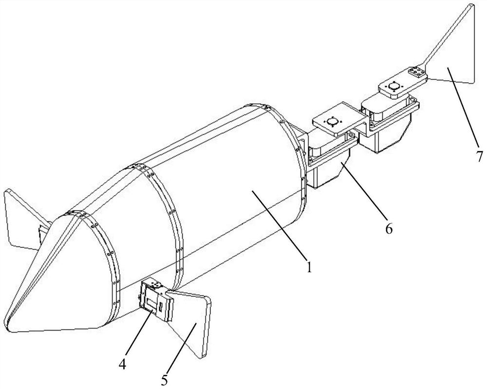
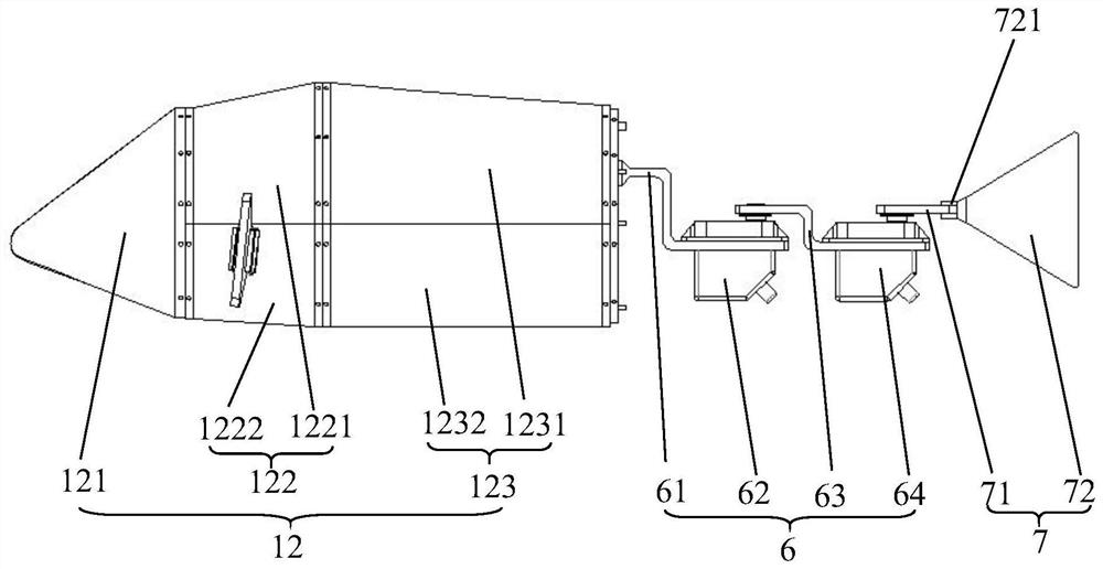
[0075] see Figure 1-Figure 12 , the embodiment of the present invention discloses a bionic robot fish with caudal and pectoral fins cooperatively propelled, including:

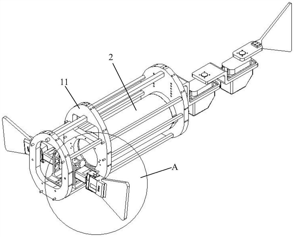
[0076] A detachable bionic fish housing 1, a cylindrical sealed cabin 2 is detachably installed in the detachable bionic fish housing 1, and a battery and a controller are fixed in the cylindrical sealed cabin 2;

[0077] There are two pectoral fin rotation driving parts 3, which are symmetr...


PUM


Abstract

The invention discloses a bionic robotic fish synergistically propelled by tail and pectoral fins. The bionic robotic fish comprises a detachable bionic fish shell which is detachably provided with a cylindrical sealed cabin, and a battery and a controller are fixed in the cylindrical sealed cabin; the bionic robotic fish further comprises two pectoral fin rotation driving parts which are symmetrically and detachably mounted on the two sides of the front part of the detachable bionic fish shell, and two pectoral fin front-back swing driving parts, and the driving ends of the two pectoral fin front-back swing driving parts are detachably connected with the driving ends of the corresponding pectoral fin rotation driving parts respectively; the bionic robotic fish further comprises two pectoral fins which are detachably connected with the corresponding pectoral fin front-back swing driving parts respectively, and a tail fin left-right swing driving part, and one side of the tail fin left-right swing driving part is detachably connected with the tail part of the detachable bionic fish shell; the bionic robotic fish further comprises a tail fin which is detachably connected with the driving end of the tail fin left-right swing driving part. All the modules of the bionic robotic fish are detachably connected, and the bionic robotic fish is simple in structure, low in cost, convenient to expand, easy to mount and dismount and capable of simulating the swimming posture of real fish.

Description

technical field [0001] The invention relates to the technical field of bionic robots, and more specifically relates to a bionic robotic fish whose tail-pectoral fins are jointly propelled. Background technique [0002] The existing oceans are rich in mineral resources, marine biological resources and energy. The development of marine resources is of great significance to the sustainable development of mankind. As an important tool for developing marine resources, the research of underwater robots has been widely concerned at home and abroad. [0003] Traditional underwater robots, such as bionic robot fish, have the following disadvantages: (1) Complex structure: Traditional underwater robots use propellers as the underwater thrusters of the propulsion system. Severe hysteresis and low energy conversion rate. In addition, many connecting components in the structure need to be customized independently, the cost of materials is high, and the technical barriers are large, so ...

Claims


Application Information

Patent Timeline
IPC IPC(8): B63G8/00B63H1/36B63G8/14B63G8/38H04N7/18
CPCB63G8/001B63H1/36B63G8/14B63G8/38H04N7/18B63G2008/002
Inventor 王连明陈磊
Owner 海南探物科技装备有限公司
Why Eureka
Try Eureka