A Design Method of Single Cantilever Beam Frame with Self-supporting Structure

A self-supporting structure and design method technology, applied in the field of additive manufacturing, can solve the problems of reducing the surface quality of the prototype, not easy to remove, etc., and achieve the effect of excellent and reasonable mechanical structure, reducing printing process and saving materials

Inactive Publication Date: 2020-03-27
XIAN UNIV OF TECH
View PDF2 Cites 0 Cited by
  • Summary
  • Abstract
  • Description
  • Claims
  • Application Information

AI Technical Summary

Problems solved by technology

However, since the supports added by these two methods need to be separated from the main body after the product is printed, the supports with sufficient strength and stability are too firmly bonded to the prototype, which is not easy to remove and easily reduces the surface quality of the prototype

Method used


Image

  • A Design Method of Single Cantilever Beam Frame with Self-supporting Structure
  • A Design Method of Single Cantilever Beam Frame with Self-supporting Structure
  • A Design Method of Single Cantilever Beam Frame with Self-supporting Structure

Examples


Embodiment 1

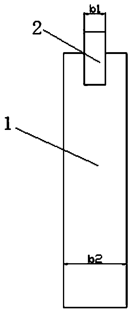
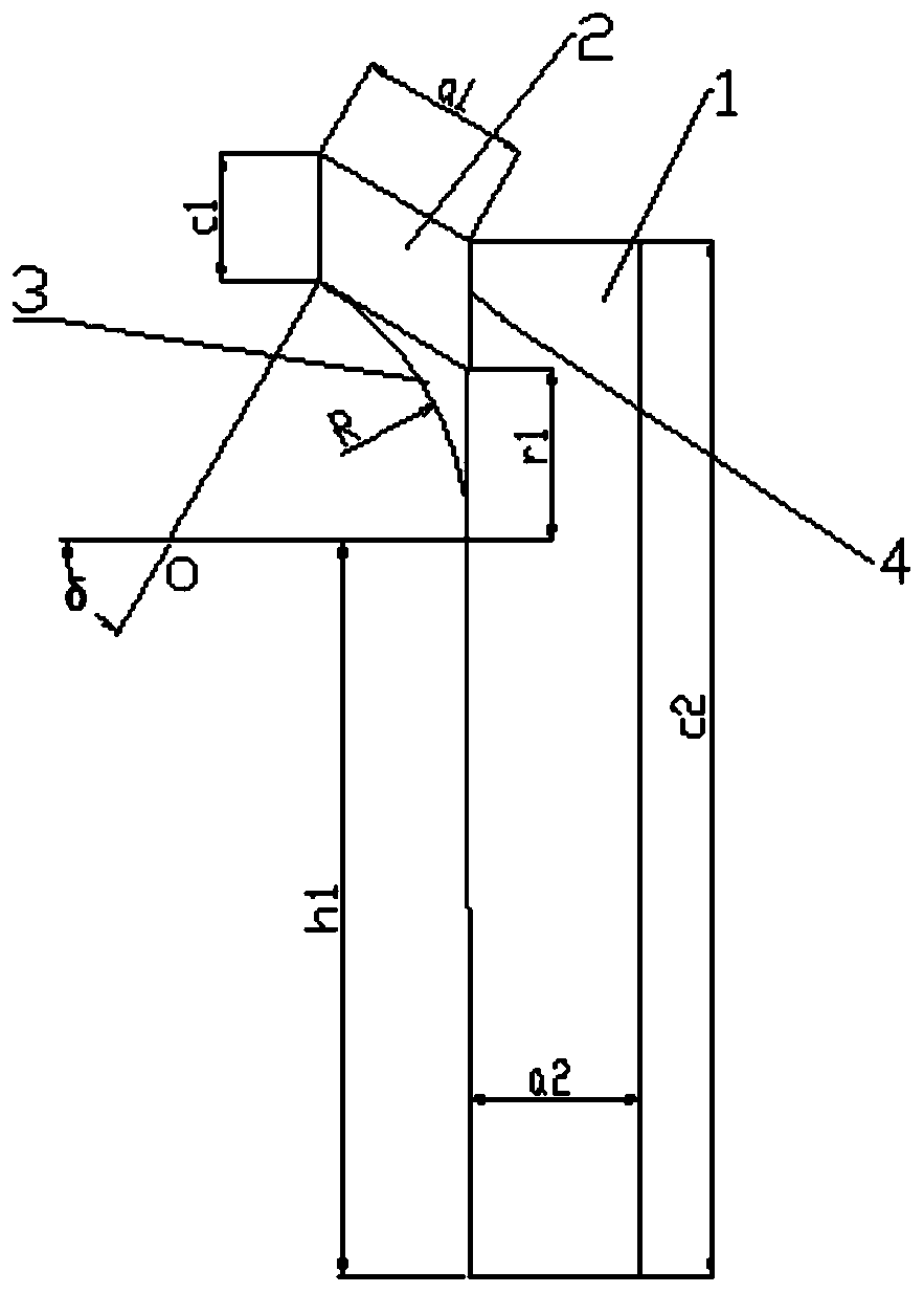
[0103] Set the design parameters of support 1, specifically including: length a 2 =20mm, width b 2 = 30mm and height c 2 = 120mm, design the structure of support 1 according to the above design parameters;

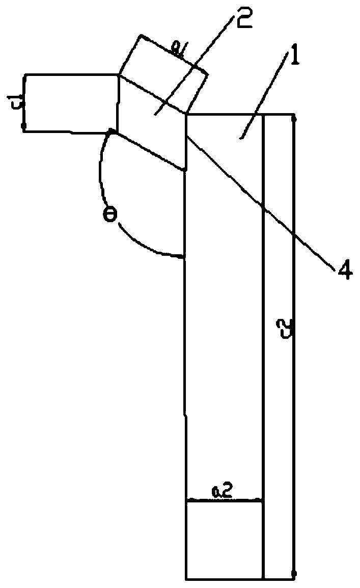
[0104] Set the parameters of the cantilever beam 2, specifically including: length a 1 =60mm, width b 1 =15mm, vertical section height difference c 1 =10mm and the included angle θ=90° between the cantilever beam and the support, design the cantilever beam structure on the top side of support 1 according to the set cantilever beam parameters

[0105] Select the weighting coefficient k of the angle θ between the cantilever beam 2 and the support 1 1 = 3; Calculate the length a of the cantilever beam 2 1 Height c from support 2 ratio of And determine the weighting coefficient k of the ratio s 2 =2; Calculate the weighting coefficient k=k of the self-supporting structure 3 1 k 2 = 4;

[0106] The selected self-supporting structure type is arc, and the single cantil...

Embodiment 2

[0113] Set the design parameters of support 1, specifically including: length a 2 =25mm, width b 2 = 30mm and height c 2 =100mm, design the structure of support 1 according to the above design parameters;

[0114] Set the parameters of the cantilever beam 2, specifically including: length a 1 =30mm, width b 1 =20mm, vertical section height difference c 1 =12mm and the included angle between the cantilever beam and the support θ=90°, design the cantilever beam structure on the top side of the support 1 according to the set cantilever beam parameters

[0115] Select the weighting coefficient k of the angle θ between the cantilever beam 2 and the support 1 1 = 3; Calculate the length a of the cantilever beam 2 1 Height c from support 2 ratio of And determine the weighting coefficient k of the ratio s 2 =2; Calculate the weighting coefficient k=k of the self-supporting structure 3 1 k 2 = 6;

[0116] The selected self-supporting structure type is an elliptical arc; a ...


PUM


Abstract

The invention discloses a design method of a single-cantilever beam frame having a self-support structure. The design method comprises the following concrete steps: 1, setting design parameters of a support seat; 2, designing a structure of the support seat according to the parameters designed in the step 1; 3, designing design parameters of a cantilever beam; 4, designing a cantilever beam structure at one side of the top of the support seat according to the parameters, designed in the step 3, of the cantilever beam; 5, designing the self-support structure between the cantilever beam and the support seat so as to obtain the single-cantilever beam frame having the self-support structure, wherein the self-support structure has a circular arc shape or an elliptic arc shape. After the single-cantilever beam frame designed by the method is adopted, the self-support structure does not need to be removed after printing is completed, so that the raw materials are saved, and the printing cost is lowered.

Description

technical field [0001] The invention belongs to the technical field of additive manufacturing, and relates to a design method of a single cantilever beam frame with a self-supporting structure. Background technique [0002] The fusion lamination molding technology is to heat and melt the filamentous hot-melt material, and at the same time, under the control of the computer, the three-dimensional nozzle selectively coats the material on the workbench according to the cross-sectional profile information, and forms a layer of cross-section after rapid cooling. . After one layer of molding is completed, the machine table is lowered to a height (that is, the thickness of the layer) and then the next layer is formed until the entire solid shape is formed. This processing method makes when the upper section is larger than the lower section, the extra part of the upper section will be suspended (or suspended) due to no material support, so that the extra section will collapse or de...

Claims


Application Information

Patent Timeline
Patent Type & Authority Patents(China)
IPC IPC(8): G06F30/20G06F30/17G06F119/18
CPCG06F30/17G06F30/20G06F2119/18
Inventor 刘琳琳李蒙李凯凯易天格万初亮
Owner XIAN UNIV OF TECH
Why Eureka
Try Eureka