Cam follower roller device

A technology of driven rollers and cams, applied in valve driving devices, valve devices, fuel injection devices, etc., can solve problems such as angle misalignment

Active Publication Date: 2017-07-14
AB SKF
View PDF9 Cites 2 Cited by
  • Summary
  • Abstract
  • Description
  • Claims
  • Application Information

AI Technical Summary

Problems solved by technology

Often there is an angular misalignment between the axis of the lifter body and the axis of the associated housing

Method used


Image

  • Cam follower roller device
  • Cam follower roller device

Examples


Embodiment Construction

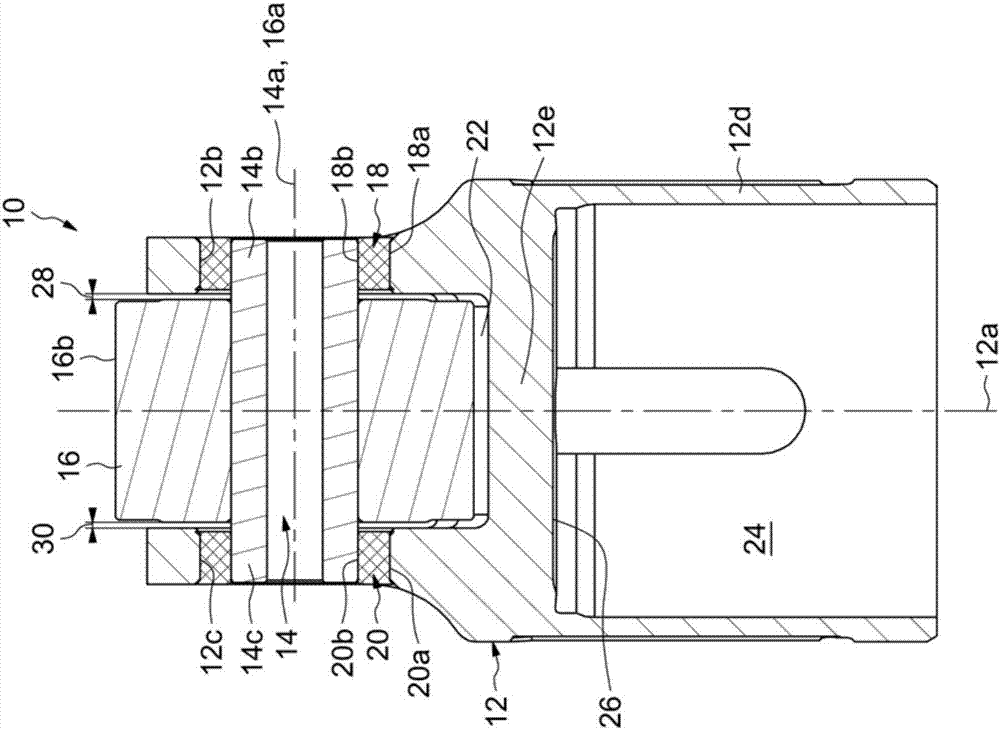
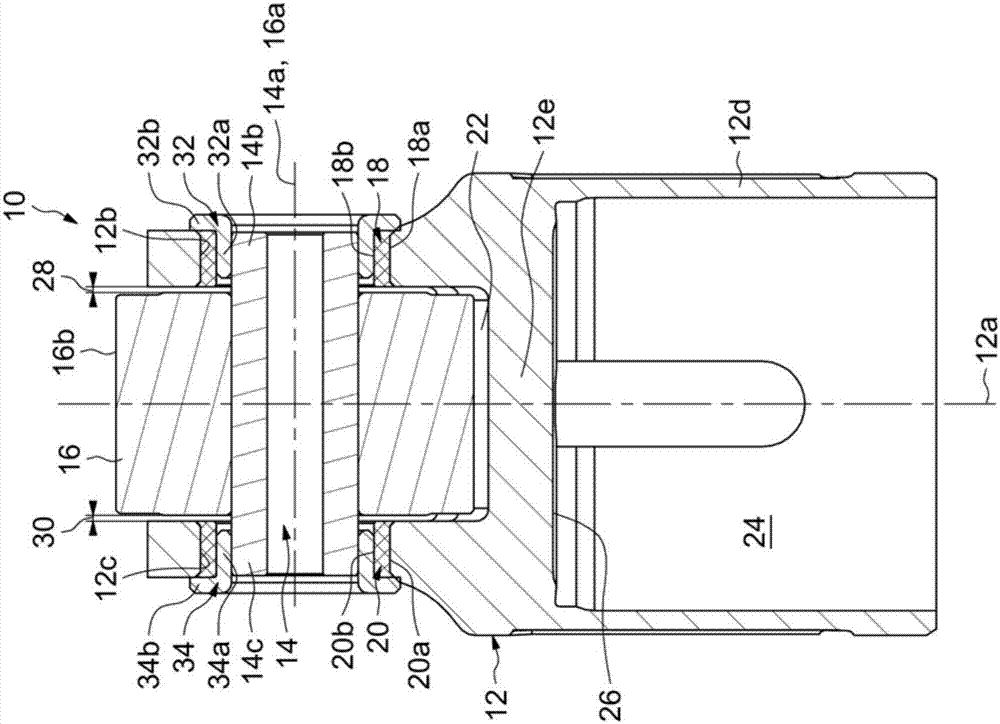
[0020] Such as figure 1 As shown, cam follower roller assembly 10 includes a tappet housing or body 12 extending along axis 12a, a shaft or pin 14 extending along axis 14a perpendicular to axis 12a, and roller 16 having axis 16a aligned with The axis 14a is coaxial, mounted on the pin and movable in rotation relative to said pin. In the disclosed embodiment, the roller 16 is mounted directly on the pin 14 . Alternatively, rolling bearings or plain bearings can be inserted radially. Roller 16 comprises an axially cylindrical outer surface (not shown) forming an associated cylinder for supporting the internal combustion engine and two opposite radial front faces (not numbered) axially delimiting said outer surface. contact surface of the cam.

[0021] The pin 14 is mounted on the tappet body 12 . The tappet body 12 supports a pin 14 . The pin 14 includes two opposing pin ends 14b, 14c and a central portion (not shown) extending between the pin ends. The central portion of ...


PUM


Abstract

The cam follower roller device comprises a tappet body 12, a pin 14 and a roller 16 mounted on said pin, the tappet body comprising holes 12b, 12c for mounting pin ends 14b, 14c of said pin on said tappet body. The device further comprises one deformable ring 18, 20 disposed between each pin end 14b, 14c of said pin and an inner wall of the associated hole 12b, 12c of said tappet body.

Description

technical field [0001] The present invention relates to the field of cam follower roller arrangements for automotive or industrial applications. Background technique [0002] An advantageous application of the invention is the use of a cam follower arrangement in a fuel injection pump for an internal combustion engine, in particular a motor vehicle internal combustion engine. Another advantageous application of the invention is the use of the device in rocker arm systems intended to control valves of internal combustion piston engines. [0003] Such cam-follower roller arrangements typically include an outer lifter body, a pin mounted on the lifter body, and a roller rotatable about its axis relative to the pin. When a cam-follower roller arrangement is used in a fuel injection pump, the roller cooperates with a cam that is synchronized with the camshaft or crankshaft of the internal combustion engine. Rotation of the camshaft or crankshaft causes periodic displacement of ...

Claims


Application Information

Patent Timeline
Patent Type & Authority Applications(China)
IPC IPC(8): F02M59/10F02M59/44F01L1/14F01L1/46F01L1/04
CPCF01L1/04F01L1/14F01L1/46F01L2301/00F02M59/102F02M59/44F02M59/445F01L2305/02F04B1/0413F04B1/0426F04B1/0435F04B1/04
Inventor N.贝吕埃C.尚邦诺M.肖莱特B.豪韦斯普尔G.欣古埃S.维奥尔特
Owner AB SKF
Why Eureka
Try Eureka