Combined type deviation rectifying device for transition section

A deviation correction device and composite technology, applied in the direction of transportation and packaging, conveyor objects, rollers, etc., can solve the problems of complex structure of photoelectric deviation correction device, inability to realize automatic deviation correction, lagging of deviation correction process, etc., to ensure contact and prevent material Dropping, reducing the effect of edge stress

Inactive Publication Date: 2015-05-27
HENGYANG CONVEYING MACHINERY
View PDF7 Cites 0 Cited by
  • Summary
  • Abstract
  • Description
  • Claims
  • Application Information

AI Technical Summary

Problems solved by technology

The deviation correcting roller set can automatically correct deviation when the load of the conveying belt is small and the deviation is small, but when the goods on the belt are heavy or the deviation of the belt transmission is large, there The friction force cannot make the idler roller rotate, so it cannot realize automatic deviation correction
[0005] CN 103303722 A discloses a conveyor belt photoelectric deviation correction device, which uses a photoelectric error correction device and a screw adjustment device to adjust the position of the conveyor belt to prevent its deviation; The structure of the photoelectric error correction device is complicated, and the photoelectric error correction device is a single-point design. When it is used for dynamic monitoring of the conveyor belt running state, there are problems of inaccurate monitoring and low precision, and there is a hysteresis phenomenon in the process of error correction.

Method used


Image

  • Combined type deviation rectifying device for transition section
  • Combined type deviation rectifying device for transition section
  • Combined type deviation rectifying device for transition section

Examples


Embodiment 1

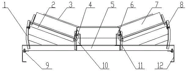
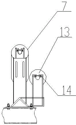
[0025] Reference Figure 1 ~ 3 , A transitional composite correction device in this embodiment, including the central beam bracket 6, mid -pillar 11, edge pillar 1, two adjustment bracket 2 and connecting steel, which is installed on the middle frame 12;The edge pillar 1 is installed at both ends of the central beam stent 6; the border pillar 1 has two rows of waist -shaped long holes;; The mid -pillar 11 has a passing hole for connecting to adjusting the bracket 2; the adjustment of the side roller 7 is installed on the bracket 2;The first connection board 6 is a U -shaped branch board. The connection of the U -shaped opening end with the pillar 11 to form a hinge axis 4 for adjusting the bracket 2 rotation, and the U line opening end of the first connection board 6 and the first connection board 6 and the first connection board 6The U -shaped opening end of the mid -pillar 11 is relatively installed; there are two fixed holes on the second connector 8, and the fastener 9 that pas...

Embodiment 2

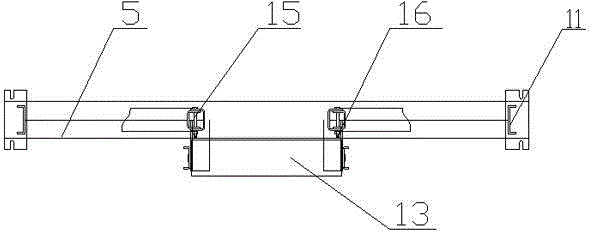
[0033] Reference Figure 1 ~ 3, A transitional composite correction device in this embodiment, including the central beam bracket 6, mid -pillar 11, edge pillar 1, two adjustment bracket 2 and connecting steel, which is installed on the middle frame 12;The edge pillar 1 is installed at both ends of the central beam stent 6; the border pillar 1 has two rows of waist -shaped long holes;Mid -roller 13 is fixed connection, and there is a passing hole for connecting to adjusting the bracket 2; the adjustment of the side roller 7 is installed on the bracket 2;8; The first connection board 6 is a U -shaped branch board, and its U -shaped opening end and the pillar 11 -pillar connection to form a hinge shaft 4 for adjusting the bracket 2, and the U line opening of the first connecting board 6 6The U -shaped opening end of the end and the mid -pillar 11 is relatively installed; there are two fixed holes on the second connector 8, and the fastener 9 that passes through the fixed hole 9 is fi...

Embodiment 3

[0041] Reference Figure 1 ~ 3 , A transitional composite correction device in this embodiment, including the central beam bracket 6, mid -pillar 11, edge pillar 1, two adjustment bracket 2 and connecting steel, which is installed on the middle frame 12;The edge pillar 1 is installed at both ends of the central beam stent 6; the border pillar 1 has two rows of waist -shaped long holes;Mid -roller 13 is fixed connection, and there is a passing hole for connecting to adjusting the bracket 2; the adjustment of the side roller 7 is installed on the bracket 2;8; The first connection board 6 is a U -shaped branch board, and its U -shaped opening end and the pillar 11 -pillar connection to form a hinge shaft 4 for adjusting the bracket 2, and the U line opening of the first connecting board 6 6The U -shaped opening end of the end and the mid -pillar 11 is relatively installed; there are two fixed holes on the second connector 8, and the fastener 9 that passes through the fixed hole 9 is f...


PUM


Abstract

The invention discloses a combined type deviation rectifying device for a transition section. The combined type deviation rectifying device comprises a middle beam bracket, center pillars, side pillars, regulating brackets and connecting profile steel; the middle beam bracket is arranged on a middle frame; the side pillars are respectively arranged at two ends of the middle beam bracket; two rows of kidney-shaped slot holes are formed in each side pillars; the center pillars are arranged in the middle of the middle beam bracket, and a through hole used for connecting the corresponding regulating bracket is formed in each center pillar; two ends of each regulating bracket are respectively provided with a first connecting plate and a second connecting plate; the U-shaped open end of each first connecting plate is connected with the through hole of the corresponding center pillar to form a hinged shaft for the corresponding regulating bracket to rotate; two fixing holes are formed in each second connecting plate, and each second connecting plate is fixedly arranged in the kidney-shaped slot holes of the corresponding side pillar through fasteners penetrating through the fixing holes, so that the corresponding regulating bracket can rotate a certain angle vertically around the hinged shaft; the connecting profile steel is welded at one side of the middle beam bracket, and is used for regulating the spacing between the central axis of a middle roll and the central axis of a side roll. The deviation rectifying device is simple in structure, convenient in operation and long in service life, and has a good automatic deviation rectifying effect.

Description

Technical field [0001] The present invention involves a conveyor belt correction device, especially the transitional composite correction device. Background technique [0002] Belt conveyor is the most important loose material transportation and loading and unloading equipment, which can be widely used in the fields of mine, metallurgy, building materials, chemicals, power, ports and other fields. [0003] The composite correction device of the transition section is mainly used for the transition section of the head and tail of the band conveyor to achieve the normal tank of the band conveyor to reduce the edge stress of the tape, ensure the full contact between the roller and the tape, improve the roller rollerThe service life is to prevent the tape from running off; the roller of the fixed transitional roller cannot be fully contacted with the tape, the edge stress of the tape is large, and the tape wear is large. [0004] CN 104003140 A discloses a band conveyor automatic corr...

Claims


Application Information

Patent Timeline
Patent Type & Authority Applications(China)
IPC IPC(8): B65G39/16
CPCB65G39/16
Inventor 廖纯徳李新宇向军王友军
Owner HENGYANG CONVEYING MACHINERY
Why Eureka
Try Eureka