
A pm2.5 reunion device
A technology for processing chambers and dust particles, which is applied in the direction of electrostatic effect separation, solid separation, and dispersed particle separation, etc., can solve the problems of low dust removal efficiency of electrostatic precipitators, achieve the effects of increasing agglomeration effect, good separation effect, and improved agglomeration efficiency
- Summary
- Abstract
- Description
- Claims
- Application Information
AI Technical Summary
Problems solved by technology
Method used
Image

Examples
Embodiment Construction
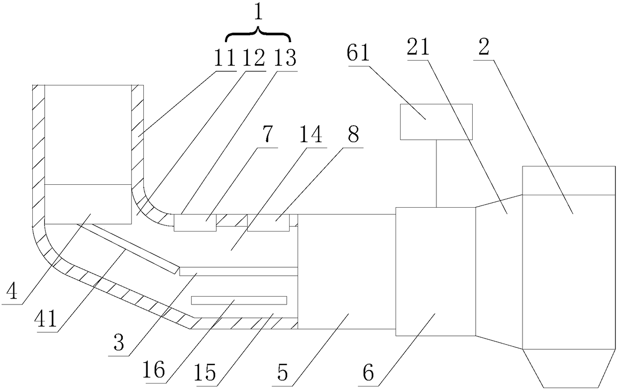
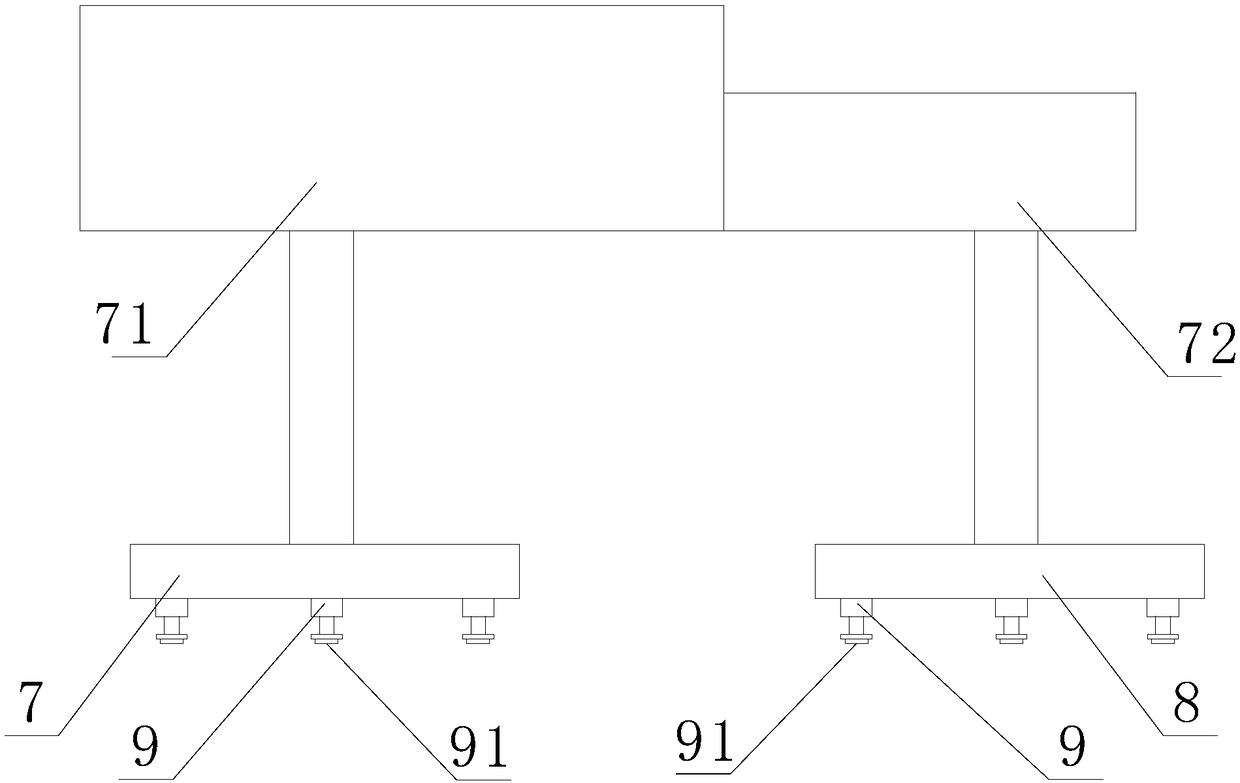
[0018] Such as figure 1 , figure 2 As shown, a PM2.5 agglomeration device includes a flue 1 and an electrostatic precipitator 2. The flue 1 includes a vertical section 11, an elbow section 12 and a horizontal section 13, and the elbow section 12 is arranged between the vertical section 11 and the horizontal section 13. Between the horizontal sections 13, an intermediate isolation layer 3 is arranged in the horizontal section 13 near one end of the elbow section 12, and the intermediate isolation layer 3 divides the horizontal section 13 into the first processing chamber 14 for fine dust particle processing and the first processing chamber 14 for coarse dust particle processing. The second processing chamber 15, and the first processing chamber 14 is arranged above the second processing chamber 15, the elbow section 12 is provided with a separator 4, and the coarse dust particles and fine dust particles in the flue 1 are automatically separated by inertia force. Separation, t...
PUM
 Abstract
Description
Claims
Application Information