

an electronic device
An electronic device and bending technology, which is applied in the fields of electrical digital data processing, instruments, computing, etc., can solve the problems of poor wearable experience of electronic devices and inability to bend electronic devices.
- Summary
- Abstract
- Description
- Claims
- Application Information
AI Technical Summary
Problems solved by technology
Method used
Image

Examples
Embodiment 1
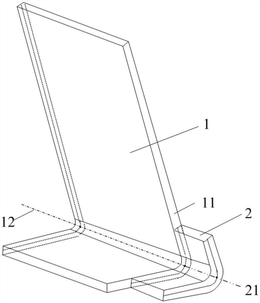
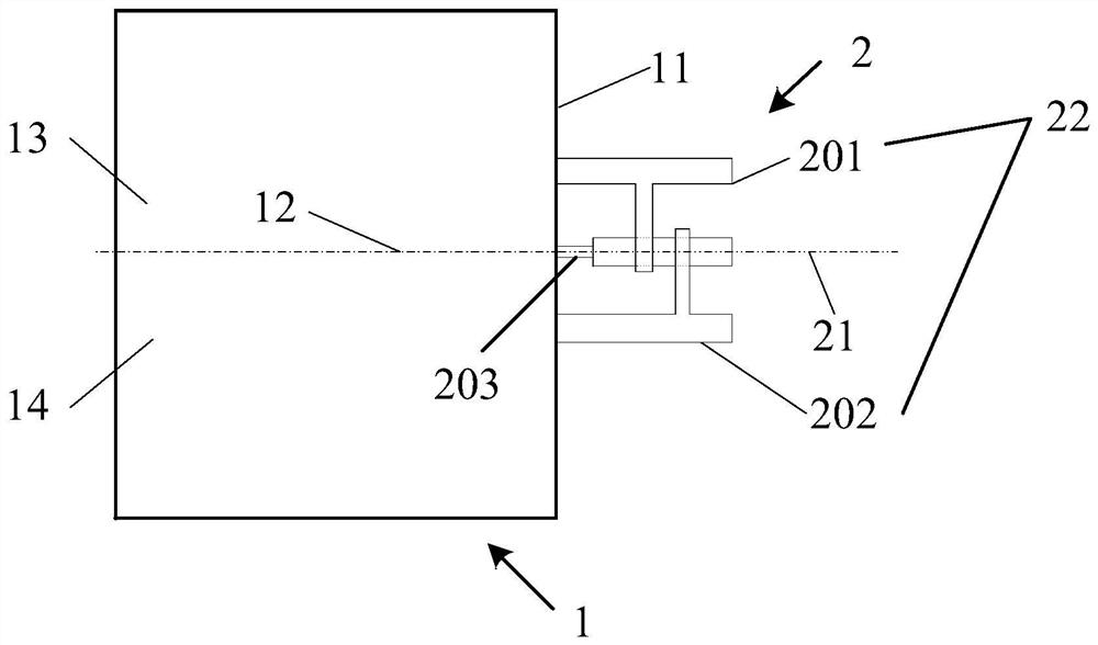
[0035] figure 1 It is a schematic structural diagram of an electronic device according to Embodiment 1 of the present invention. figure 2 It is a schematic diagram of an optional structure of the electronic device in the embodiment of the present invention.
[0036] An embodiment of the present invention provides an electronic device, see figure 1 As shown, the electronic device of the embodiment of the present invention includes: a body 3 (not shown in the figure), a flexible screen 1 and a first bending device 2 , and the flexible screen 1 is disposed on the body 3 .
[0037] The flexible screen 1 includes at least a first end surface 11 . The first bending device 2 is disposed on the first end surface 11 .
[0038] Wherein, when the flexible screen 1 is bent under force, the flexible screen 1 drives the first bending device 2 to bend; the first bending center 12 of the flexible screen 1 coincides with the second bending center 21 of the first bending device 2 Or differ...
Embodiment 2
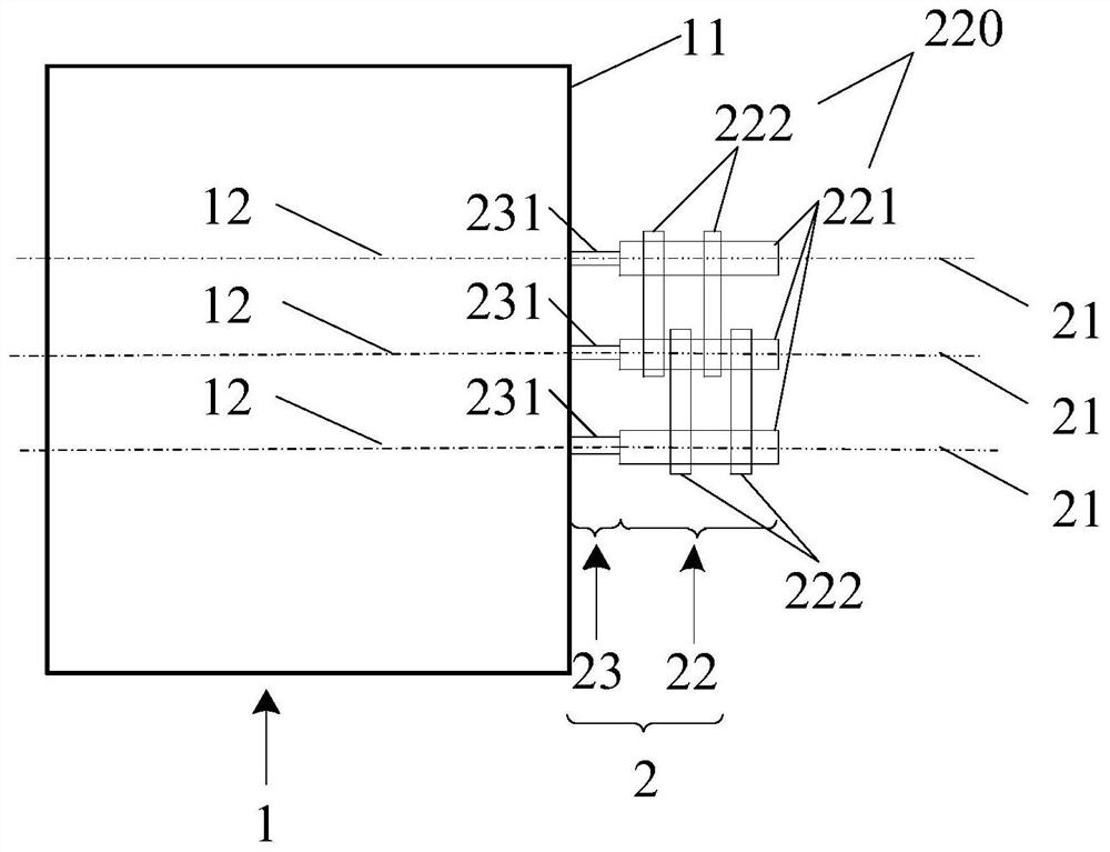
[0052] image 3 It is a schematic structural diagram of the electronic device in Embodiment 2 of the present invention.
[0053] In the electronic device of the embodiment of the present invention, the first bending device 2 may include: a connecting shaft group 23 and a limiting connector 22; the connecting shaft group 23 may include M first connecting shafts 231 with one end disposed on the first end surface 11 , the other ends of the M first connecting shafts 231 are connected to the limit connecting member 22, and M is an integer greater than or equal to 1.
[0054] In the embodiment of the present invention, it should be noted that when M is equal to 1, the limiting connector 22 can specifically adopt figure 2 structure shown.
[0055] When M is equal to 2, optionally, the number of the first bending centers can be 2, that is, the axis of any first connecting shaft 231 corresponds to a first bending center 12, and the limiting connector 22 can include two two second b...
Embodiment 3
[0075] Figure 9 It is a schematic structural diagram of an electronic device in Embodiment 3 of the present invention. Figure 10 It is a schematic structural diagram of the second bending device in Embodiment 3 of the present invention. Figure 11 It is a schematic structural diagram of an optional electronic device in Embodiment 3 of the present invention. Figure 12 It is another optional structural schematic diagram of the electronic device in Embodiment 3 of the present invention. Figure 13 It is a schematic structural diagram of the housing in Embodiment 3 of the present invention.
[0076] exist Figure 1 to Figure 8 Based on the example shown, as Figure 9 to Figure 12 As shown, in the electronic device of this embodiment, the flexible screen 1 may further include: a second end face 15 parallel to the first end face 11;
[0077] The connecting shaft group 23 may also include: M second connecting shafts 232 arranged on the second end face 15; the axis center of t...
PUM
 Abstract
Description
Claims
Application Information