Chopping amplifying circuit and its implementation method

A technology of amplifier circuit and low-pass filter circuit, which is applied in the field of analog circuit design, can solve the problems of precise control of amplifier magnification, influence on circuit stability, and insignificant effect, etc., achieve simple structure, reduce design difficulty, and improve input impedance Effect

Active Publication Date: 2017-10-24
SOUTH CHINA UNIV OF TECH
View PDF5 Cites 18 Cited by
  • Summary
  • Abstract
  • Description
  • Claims
  • Application Information

AI Technical Summary

Problems solved by technology

If the input impedance is increased by reducing the input capacitance, the parasitic parameters of the circuit will affect the precise control of the amplification factor of the amplifier, and the effect is not obvious
Therefore, the usual chopper amplifier uses a positive feedback loop to increase the input impedance, the structure is complex and the introduction of positive feedback will affect the stability of the circuit

Method used


Image

  • Chopping amplifying circuit and its implementation method
  • Chopping amplifying circuit and its implementation method
  • Chopping amplifying circuit and its implementation method

Examples


Embodiment 1

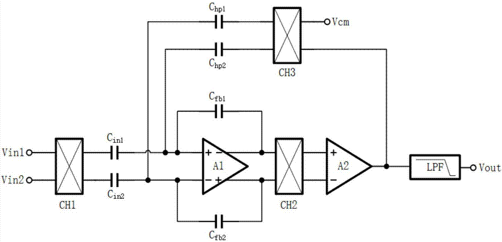
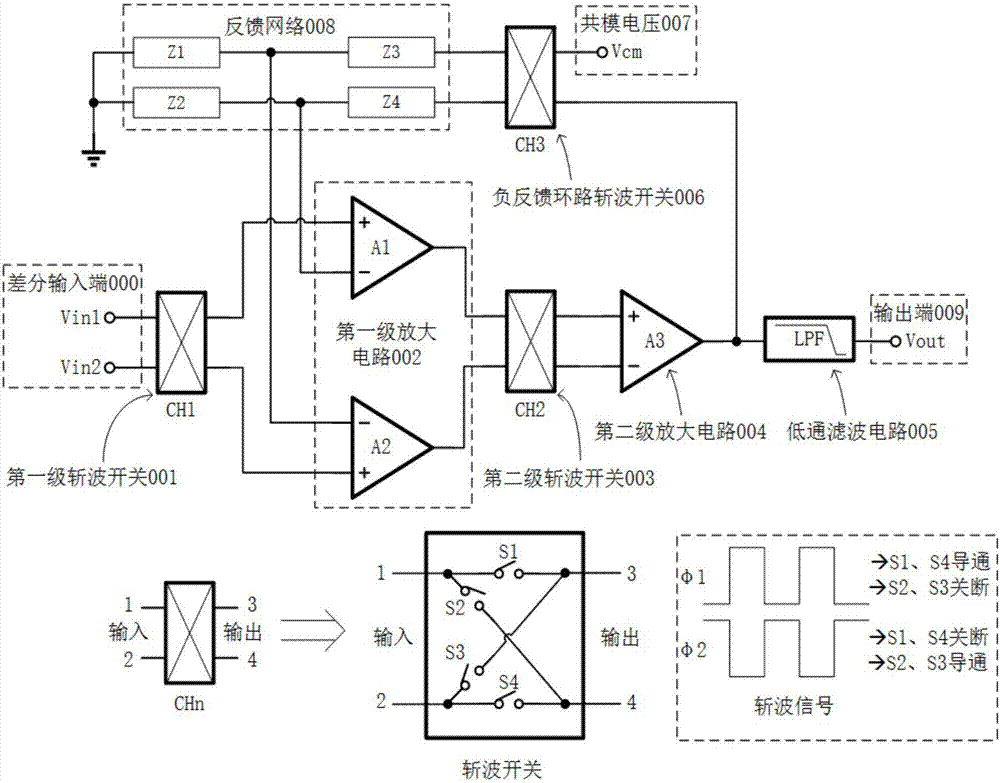
[0049] This embodiment is based on the traditional integrated chopper amplifier circuit (structural diagram as figure 1 As shown), an improvement of a chopper amplifier circuit is provided, and the structural block diagram is as follows image 3 shown, including:

[0050] The differential input terminal 000 is used to connect the differential voltage signal that needs to be amplified to the chopper amplifier circuit;

[0051] The first-stage chopping switch 001 is used to modulate the frequency spectrum of the input differential voltage signal to the odd harmonic frequency of the chopping signal;

[0052] The first-stage amplifying circuit 002 is used to connect the modulated signal to the non-inverting input terminals of the two internal differential operational amplifiers for amplification, and at the same time connect the feedback signal of the negative feedback loop to the inverting input terminals of the two internal differential operational amplifiers. phase input to s...

Embodiment 2

[0066] In this embodiment, on the basis of a chopper amplifier circuit in Embodiment 1, an input capacitor pair 012, an ultra-low frequency low-pass filter circuit 010, and a DC suppression loop chopper switch 011 are added, inside the first-stage amplifier circuit 002 Added pseudo-resistor PRES for DC biasing of the op amp, local feedback capacitor C of the op amp fb3 and C fb4 , and a capacitor is used to realize the feedback network 008.

[0067] Such as Figure 4 As shown, a chopper amplifier circuit of this embodiment includes a differential input terminal 000, a first-stage chopper switch 001, an input capacitor pair 012, a first-stage amplifying circuit 002, a second-stage chopper switch 003, a second-stage Amplifying circuit 004, low-pass filter circuit 005, negative feedback loop chopper switch 006, common mode voltage 007, feedback network 008, ultra-low frequency low-pass filter circuit 010, DC suppression loop chopper switch 011 and output terminal 009. The chop...

Embodiment 3

[0142] This embodiment provides a method for implementing a chopping amplifier circuit, the flow chart is as follows Figure 8 shown, including the following steps:

[0143] S1. The differential voltage signal that needs to be amplified is connected to the chopper amplifier circuit from the differential input terminal 000;

[0144] S2. The spectrum of the input differential voltage signal is modulated to the odd harmonic frequency of the chopping signal through the first stage chopping switch 001;

[0145] S3. The modulated signal is input to the first-stage amplifying circuit 002 for amplification, and at the same time, the gain of the chopper amplifier is stabilized through a negative feedback loop;

[0146] S4. The amplified modulated signal is demodulated by the second-stage chopping switch 003 to obtain the amplified initial differential signal, and the noise and offset voltage generated by the first-stage amplifying circuit 002 are modulated to the odd harmonic frequenc...


PUM


Abstract

The invention discloses a chopping amplifying circuit. A differential signal is connected to a circuit from a differential input end, and the differential input end is connected with an input end of a first-grade chopping switch; an output signal of the first-grade chopping switch is connected to the same-phase input ends of two differential operation amplifiers of a first-grade amplification circuit, and output ends of two differential operation amplifiers in the first-grade amplification circuit are connected to an input end of a second-grade chopping switch; an output signal of the second-grade chopping switch is connected to the same-phase and reverse-phase input ends of a second-grade amplification circuit; an output end of the second-grade amplification circuit is connected with input ends of a low pass filtering circuit and a negative feedback loop chopping switch, the other input end of the negative feedback loop chopping switch is connected with a common mode voltage; an output signal of the negative feedback loop chopping switch is connected to reverse-phase input ends of the two differential operation amplifiers in the first-grade amplification circuit after passing through pressure differential of a feedback network, and the low-pass filter wave circuit outputs a final amplifying signal of the chopping amplifying circuit.

Description

technical field [0001] The invention relates to the field of analog circuit design, in particular to a chopping amplifier circuit and a realization method thereof, which are mainly used for low-noise amplification of weak signals, especially low-noise amplification of high-impedance weak signals. Background technique [0002] Chopper amplification technology was proposed by E.A.Goldberg in 1948. With the continuous development of integrated circuit technology, it will soon be applied to chip integration technology. Chopper amplification technology is a modulation technology that improves the performance of operational amplifiers. Its basic principle is to use an AC modulation signal to modulate low-frequency noise and offset voltage to high-frequency, and then filter to eliminate its influence. It is mainly used for low-frequency weak Low noise amplification of the signal. [0003] The implementation of the full integrated circuit of the chopper amplifier is usually as fol...

Claims


Application Information

Patent Timeline
Patent Type & Authority Applications(China)
IPC IPC(8): H03F1/26H03F1/34H03F3/393H03F3/45
CPCH03F1/26H03F1/342H03F3/393H03F3/45183H03F2200/372
Inventor 梁志明李斌吴朝晖
Owner SOUTH CHINA UNIV OF TECH
Why Eureka
Try Eureka