Improved new energy automobile charging device

A new energy vehicle and charging device technology, applied in electric vehicle charging technology, charging station, coupling device and other directions, can solve the problems of charging gun head detachment, easy arc generation, user safety accidents, etc., to reduce the workload of personnel, The effect of improving operation stability and preventing electric shock accidents

Inactive Publication Date: 2017-11-10
深圳市昌圣欣科技有限公司
View PDF5 Cites 17 Cited by
  • Summary
  • Abstract
  • Description
  • Claims
  • Application Information

AI Technical Summary

Problems solved by technology

Because new energy electric vehicles are powered by electricity, the supporting charging equipment, that is, charging stations and charging piles, need to be matched to keep up. Otherwise, the inconvenient use of users will greatly affect the promotion of new energy electric vehicles. The existing charging piles can charge electric vehicles. During the process, it is manually plugged and unplugged by personnel. During the plugging and unplugging process, the charging head is prone to arc due to the influence of voltage. Casualties, and there is no protection device in the charging state, it is easy to cause the charging gun head to fall off or be damaged due to accidental touch

Method used


Image

  • Improved new energy automobile charging device
  • Improved new energy automobile charging device
  • Improved new energy automobile charging device

Examples


Embodiment Construction

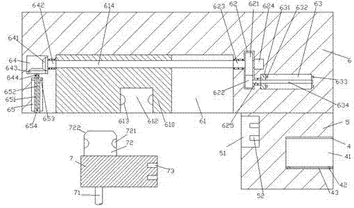
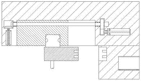
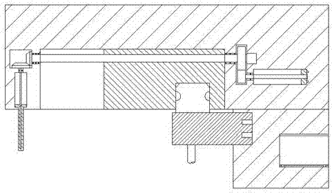
[0025] Such as Figure 1-Figure 5 As shown, an improved new energy vehicle charging device of the present invention includes a support column 5, a charging mechanism 6 fixed on the top of the support column 5 and extending to the left, and used to cooperate with the charging mechanism 6 The charging gun 7 of the support column 5 is provided with an insertion slot 51 in the left end surface of the support column 5, and a second conductive pin 52 is provided on the inner wall of the right side of the insertion slot 51, and the insertion slot 51 on the right side A storage part is provided in the supporting column 5, and a guide chute 61 is provided in the bottom end surface of the left extension section of the charging mechanism 6, and a first screw 614 extending left and right is provided in the guide chute 61. The screw rod 614 is threadedly connected with a propulsion block 610, the charging mechanism 6 on the left side of the guide chute 61 is provided with a first transmiss...


PUM


Abstract

The invention discloses an improved new energy automobile charging device. The improved new energy automobile charging device comprises a support post, a charging mechanism and a charging gun, wherein the charging mechanism is fixed at a top part of the support post and extends towards a left side, the charging gun is used for being connected with the charging mechanism in a matching way, a connection groove is formed in an end surface of a left side of the support post, a second conductive pin is arranged on an inner wall of a right side of the connection groove, a storage part is arranged in the support post at the right side of the connection slot, a sliding guide groove is formed in an end surface of a bottom part of an extending segment of a left side of the charging mechanism, a first screw rod is arranged in the sliding guide groove and extends leftwards and rightwards, a push block is in threaded connection with the first screw rod in a matching way, a first transmission cavity is formed in the charging mechanism at a left side of the sliding guide groove, a first sliding cavity is formed in the charging mechanism below the first transmission cavity, a second transmission cavity is formed in the charging mechanism at a right side of the sliding guide groove, a first rotation shaft is arranged in the second transmission cavity and extends leftwards and rightwards, and a right side end of the first rotation shaft is connected with a motor. The improved new energy automobile charging device is simple in structure, automatic control of connection can be achieved, power supply connection is automatically controlled, a baffle plate is automatically controlled to extend, and the improved new energy automobile charging device is high in working efficiency and high in safety.

Description

technical field [0001] The invention relates to the technical field of new energy vehicle charging, in particular to an improved charging device for new energy vehicles. Background technique [0002] New energy electric vehicles refer to vehicles powered by on-board power supplies and driven by motors. Since new energy electric vehicles are powered by electricity and have little impact on the environment, their prospects are widely optimistic, and they also meet the requirements of new energy strategies. Because new energy electric vehicles are powered by electricity, the supporting charging equipment, that is, charging stations and charging piles, need to be matched to keep up. Otherwise, the inconvenient use of users will greatly affect the promotion of new energy electric vehicles. The existing charging piles can charge electric vehicles. During the process, it is manually plugged and unplugged by personnel. During the plugging and unplugging process, the charging head i...

Claims


Application Information

Patent Timeline
IPC IPC(8): H01R43/26H01R13/629H01R13/642B60L11/18
CPCB60L53/31H01R13/629H01R13/642H01R43/26Y02T10/70Y02T10/7072Y02T90/12
Inventor 郑晓春
Owner 深圳市昌圣欣科技有限公司
Why Eureka
Try Eureka