Novel welding device

A welding device and a new type of technology, applied in the direction of welding accessories, etc., can solve the problems of easy arc generation, high welding machine, electric shock for users, etc., and achieve the effect of improving operation stability, reducing personnel workload, and improving work efficiency

Inactive Publication Date: 2017-09-01
诸暨市柯晶机械技术开发有限公司
View PDF5 Cites 0 Cited by
  • Summary
  • Abstract
  • Description
  • Claims
  • Application Information

AI Technical Summary

Problems solved by technology

[0002] At present, electric welding machines are used more and more widely, and they rely on plug-in power supply to work normally. Therefore, whether the electric welding machine is plugged in stably and whether the power supply is safe is the basis for determining whether the electric welding machine can work normally. The plug-in power supply generally relies on manual plug-in. However, due to the high voltage required by the electric welding machine, the stability of manu

Method used


Image

  • Novel welding device
  • Novel welding device
  • Novel welding device

Examples


Example Embodiment

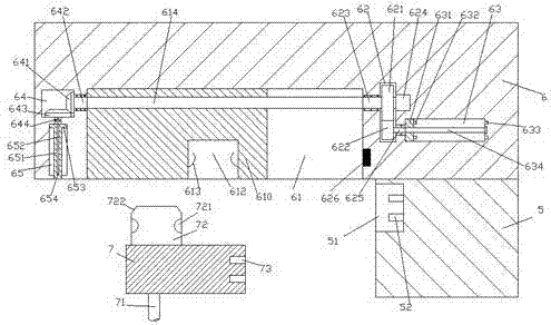
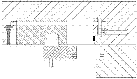
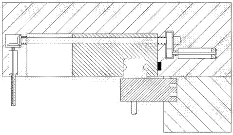
[0024] Such as Figure 1-Figure 5 As shown, a new type of welding device of the present invention includes a support column 5, a cross beam 6 fixed on the top of the support column 5 and extended to the left side, and a plug 7 matingly connected with the cross beam 6. The support column 5 An insertion groove 51 is provided in the left end surface, a second insertion piece 52 is provided on the right inner wall of the insertion groove 51, and a sliding groove 61 is provided in the bottom end surface of the left side extension of the cross beam 6. The sliding groove 61 is provided with a first spiral rod 614 extending left and right, the spiral pattern on the first spiral rod 614 is connected with a pushing block 610, and the beam 6 on the left side of the sliding groove 61 is provided with a first transmission force Cavity 64, the beam 6 below the first force transmission cavity 64 is provided with a first sliding cavity 65, and the beam 6 on the right side of the sliding groove...


PUM


Abstract

The invention discloses a novel welding device. The novel welding device comprises a supporting pillar, a cross beam which is fixed to the top of the supporting pillar and extends towards the left side, and an inserting head which is matched with the cross beam for connection. An inserting-in groove is formed in the left side end face of the supporting pillar. Second inserting sheets are arranged on the inner wall of the right side of the inserting-in groove. A sliding groove is formed in the bottom end face of an extended section at the left side of the cross beam, and a first screw rod extending left and right is arranged in the sliding groove. The first screw rod is connected with a pushing block in a screw thread fit mode. A first force transfer cavity is formed in the cross beam and located at the left side of the sliding groove. A first sliding cavity is formed in the cross beam and located below the first force transfer cavity. A second force transfer cavity is formed in the cross beam and located at the right side of the sliding groove. A first rotating shaft extending left and right is arranged in the second force transfer cavity. The right side end of the first rotating shaft is connected with a driver. The novel welding device is novel in structure, automatic inserting control can be achieved, power supply connection and curtain board stretching can be controlled automatically, and the working efficiency and safety are high.

Description

technical field [0001] The invention relates to the field of welding technology, in particular to a novel welding device. Background technique [0002] At present, electric welding machines are used more and more widely, and they rely on plug-in power supply to work normally. Therefore, whether the electric welding machine is plugged in stably and whether the power supply is safe is the basis for determining whether the electric welding machine can work normally. The plug-in power supply generally relies on manual plug-in. However, due to the high voltage required by the electric welding machine, the stability of manual plug-in is poor, and arcs are likely to be generated during the plug-in process. The generation of arcs is likely to cause electric shock to users. The user has a certain potential danger, which will cause safety accidents and cause casualties. Moreover, there is no protection device when the power supply is plugged in, and it is easy to loosen or cause damag...

Claims


Application Information

Patent Timeline
IPC IPC(8): B23K9/32
CPCB23K9/32
Inventor 陈嘉伟
Owner 诸暨市柯晶机械技术开发有限公司
Why Eureka
Try Eureka