Automatic current applying method for composite copper foil equipment

A technology of composite copper foil and current application, applied in the direction of sustainable manufacturing/processing, parallel operation of DC power supply, climate sustainability, etc., can solve the problems of long time consumption, film breakage, fluctuations, etc. The effect of staff workload

Pending Publication Date: 2022-04-12
CHONGQING JIMAT NEW MATERIAL TECH CO LTD
View PDF0 Cites 0 Cited by
  • Summary
  • Abstract
  • Description
  • Claims
  • Application Information

AI Technical Summary

Problems solved by technology

[0003] In the existing continuous coating equipment and process, using the constant current output function of high-frequency DC power supply, it is necessary to calculate the current reasonably according to the incoming material situation, and manually increase the outp

Method used


Image

  • Automatic current applying method for composite copper foil equipment

Examples


Example Embodiment

[0026] Example 1

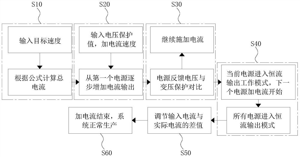
[0027] refer to figure 1 As shown, the present invention discloses an automatic current application method for composite copper foil equipment, which changes the manual current application mode in the continuous coating process to the automatic current application mode, so as to realize the automatic sharing of the total current output of each power supply. Specifically, the method includes the following steps:

[0028] S10, the calculation of the total current, determine the line speed of the composite copper film operation, and calculate the total current to be applied to the entire copper plating production line;

[0029] In the production process of acid copper electroplating of composite conductive film, the current applied to the whole line can be calculated according to the empirical formula for each copper layer with a thickness of one micron. The total current I = constant N * line speed * product width, in In the segmented continuous coating proc...

Example Embodiment

[0041] Example 2

[0042] refer to figure 1 As shown, the present invention discloses an automatic current application method for composite copper foil equipment, which changes the manual current application mode in the continuous coating process to the automatic current application mode, so as to realize the automatic sharing of the total current output of each power supply. Specifically, the method includes the following steps:

[0043] S10, the calculation of the total current, determine the line speed of the composite copper film operation, and calculate the total current to be applied to the entire copper plating production line;

[0044] In the production process of acid copper electroplating of composite conductive film, the current applied to the whole line can be calculated according to the empirical formula for each copper layer with a thickness of one micron. The total current I = constant N * line speed * product width, in In the segmented continuous coating proc...

Example Embodiment

[0055] Example 3

[0056] The present invention also provides an embodiment, and the difference between this embodiment and the above two embodiments is only in step S50 and the value of the constant N. The constant N in this embodiment is 1.5. In this embodiment, the step The contents of the S50 are as follows:

[0057] S50, adjust the difference between the input current and the actual current;

[0058] If the applied current is greater than the calculated total current, the power supply of the entire line reduces the current in the order from back to front. When reducing the current, the minimum allowable reduction can be set, so that the current output of each power supply is gradually reduced, and finally the actual application is achieved. The current reaches the calculated total current.

[0059] In addition, it should be noted that, in this embodiment, step S50 can be replaced with:

[0060] S50, adjust the difference between the input current and the actual current...


PUM


Abstract

The invention provides an automatic current applying method for composite copper foil equipment, and relates to the technical field of electroplating. The method comprises the following steps: S10, calculating a total current, determining the linear speed of the operation of a composite copper film, and calculating the total current to be applied to the whole copper plating production line; s20, current output is gradually increased from the first power source, and current is gradually applied in a gradient mode in the constant-speed movement process of the product; s30, comparing the feedback voltage of the power supply with transformation protection; s40, when the current power supply enters the constant-current output working mode, the next power supply starts to add current; s50, adjusting the difference value between the input current and the actual current; s60, current adding is finished, and the system performs normal production; the device has the beneficial effects that automatic current application can be realized, the current application time is shortened, and the workload of personnel is reduced.

Description

technical field [0001] The invention relates to the technical field of electroplating, and more specifically, the invention relates to a method for automatically applying current to composite copper foil equipment. Background technique [0002] In the existing electroplating production process of copper foil or composite copper foil, the conductive roller conducts electricity to the foil, the foil passes through the plating solution, and in the anode area, the surface of the foil achieves the purpose of thickening the copper plating. [0003] In the existing continuous coating equipment and process, using the constant current output function of high-frequency DC power supply, it is necessary to calculate the current reasonably according to the incoming materials, and manually increase the output current of the rectifier slowly to avoid a sharp rise in voltage when the current is too large The resulting membrane surface is burned or even broken, and the process of applying cu...

Claims


Application Information

Patent Timeline
IPC IPC(8): H02J1/10
CPCY02P80/10
Inventor 臧世伟李军
Owner CHONGQING JIMAT NEW MATERIAL TECH CO LTD
Why Eureka
Try Eureka