Control structure and method for virtual synchronous machine of voltage source converter based high voltage direct current (VSC-HVDC) system

A technology of VSC-HVDC and virtual synchronous machine, which is applied to the control of the above-mentioned VSC-HVDC system virtual synchronous machine and the field of VSC-HVDC system virtual synchronous machine control structure to achieve the effect of improving stability and enhancing reliability

Active Publication Date: 2017-11-10
XIAN XJ POWER ELECTRONICS TECH
View PDF2 Cites 16 Cited by
  • Summary
  • Abstract
  • Description
  • Claims
  • Application Information

AI Technical Summary

Problems solved by technology

[0005] However, the current academic research on virtual synchronous machine technology only focuses on a single VSC or its frequency modulation and voltage regulation control

Method used


Image

  • Control structure and method for virtual synchronous machine of voltage source converter based high voltage direct current (VSC-HVDC) system
  • Control structure and method for virtual synchronous machine of voltage source converter based high voltage direct current (VSC-HVDC) system
  • Control structure and method for virtual synchronous machine of voltage source converter based high voltage direct current (VSC-HVDC) system

Examples


Embodiment 1

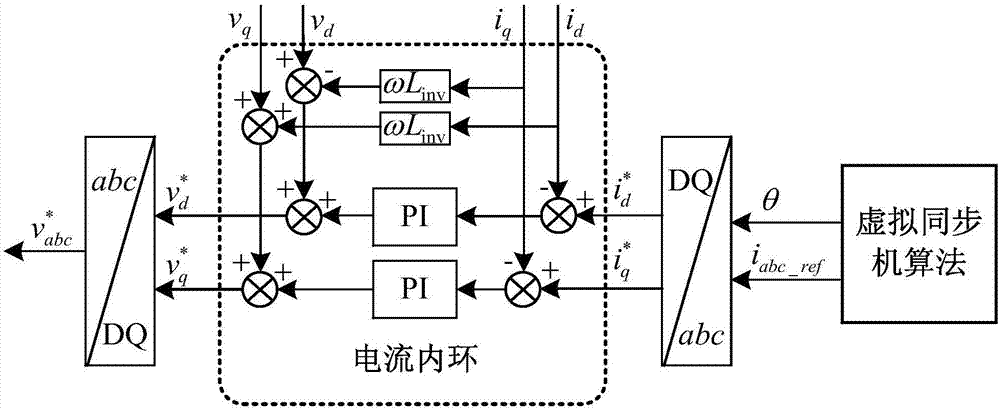
[0041] Active power control is a combination of power controller, DC voltage deviation controller and VSC virtual synchronous machine f-P droop controller. The specific control method of this method is:

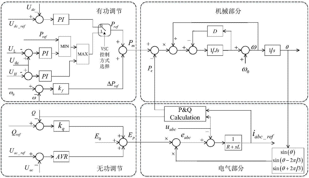
[0042] Step 1, determine the mechanical equation and electromagnetic equation of the VSC virtual synchronous machine, expressed as Where J is the moment of inertia of the VSC virtual synchronous machine, D is the damping coefficient, r t is the synchronous resistance, l t is the synchronous reactance, ω is the angular velocity, P m is the mechanical power, P e is the electromagnetic power, ω N is the rated angular velocity, ω r is the grid angular velocity, e abc , v abc i abc are the three-phase terminal potential, voltage and current of the VSC virtual synchronous machine, respectively, j, d, t; where v abc is the measured VS output voltage of the virtual synchronous machine, e abc Via the VSC virtual synchronous machine potential input E p and angular velocity ω...

Embodiment 2

[0049] Active power regulation is a combination of DC voltage controller and VSC virtual synchronous machine f-P droop controller. The control method is specifically:

[0050] Step 1, determine the mechanical equation and electromagnetic equation of the VSC virtual synchronous machine, expressed as Where J is the moment of inertia of the VSC virtual synchronous machine, D is the damping coefficient, r t is the synchronous resistance, l t is the synchronous reactance, ω is the angular velocity, P m is the mechanical power, P e is the electromagnetic power, ω N is the rated angular velocity, ω r is the grid angular velocity, e abc , v abc i abc are the three-phase terminal potential, voltage and current of the VSC virtual synchronous machine, respectively, j, d, t; where v abc is the measured VS output voltage of the virtual synchronous machine, e abc Via the VSC virtual synchronous machine potential input E p and angular velocity ω to get: in

[0051] Step 2, th...


PUM


Abstract

The invention discloses a control structure and method for a virtual synchronous machine of a voltage source converter based high voltage direct current (VSC-HVDC) system. The control structure comprises a VSC virtual synchronous machine, wherein the VSC virtual synchronous machine is connected with a power grid through a grid-connected gateway KS. The control system of the control structure comprises an active power regulation module, a reactive power regulation module, a mechanical module and an electrical module. By inertia and impedance characteristics of a VSC simulation synchronous power generator and functions of frequency regulation and voltage regulation, the stability of an AC power system is improved, and seamless switching of grid-connected and island modes is achieved. The method comprises a DC voltage control method and an active power control method, can be used for all VSC applications in the VSC-HVDC system and has the function of coordinated control on a DC voltage, and the running reliability of a DC system is improved.

Description

technical field [0001] The invention belongs to the technical field of high-voltage power transmission, and relates to a control structure of a virtual synchronous machine of a VSC-HVDC system; the invention also relates to a control method of the above-mentioned virtual synchronous machine of the VSC-HVDC system. Background technique [0002] With the adjustment of my country's energy structure and the advancement of power grid construction planning, the flexible DC transmission system has been widely used due to its advantages of independent and flexible controllable active power and reactive power, no need for grid commutation voltage, and power supply to isolated island areas. Developing in the direction of high pressure and large capacity. [0003] At present, VSC-HVDC mostly adopts conventional direct current control based on PI double-loop decoupling under the synchronous rotating coordinate system. In this type of control, the active and reactive power control targets...

Claims


Application Information

Patent Timeline
Patent Type & Authority Applications(China)
IPC IPC(8): H02J3/38H02J3/40H02J3/36
CPCH02J3/36H02J3/38H02J3/388H02J3/40Y02E60/60
Inventor 姚为正杨美娟王先为吴金龙马焕
Owner XIAN XJ POWER ELECTRONICS TECH
Why Eureka
Try Eureka