Charging device for new energy vehicle

A new energy vehicle and charging device technology, which is applied to electric vehicle charging technology, charging stations, electric vehicles, etc., can solve the problems of user safety accidents, easy arc generation, and user electric shock, so as to improve installation speed and improve work efficiency. Efficiency and easy operation

Inactive Publication Date: 2017-11-21
深圳市昌圣欣科技有限公司
View PDF0 Cites 1 Cited by
  • Summary
  • Abstract
  • Description
  • Claims
  • Application Information

AI Technical Summary

Problems solved by technology

New energy vehicles are inseparable from charging piles. In the process of charging new energy vehicles with existing charging piles, they are manually plugged in by personnel. During the plugging process, the charging head is prone to arc due to the influence of voltage, and the generation of arc is easy to cause The electric shock of the user has a certain potential danger to the user, which will cause safety accidents and cause casualties. Moreover, most of the power supply sockets of the existing charging piles are manually operated protective covers, which are cumbersome to operate and are easily damaged. When the protective cover is damaged Finally, if it cannot be replaced or maintained in time, there will be a greater safety hazard

Method used


Image

  • Charging device for new energy vehicle
  • Charging device for new energy vehicle
  • Charging device for new energy vehicle

Examples


Embodiment Construction

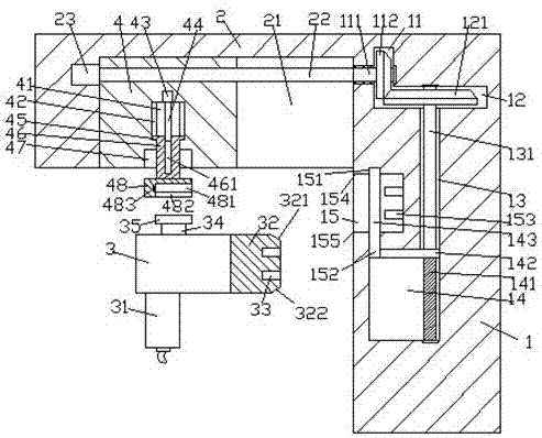
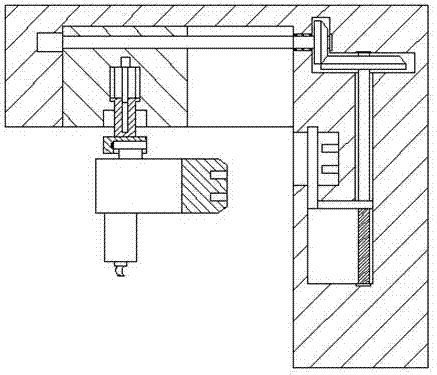
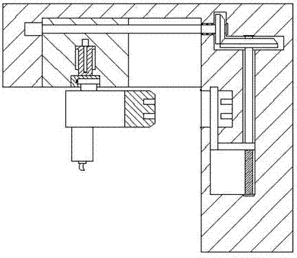
[0024] like Figure 1-Figure 7 As shown, a new energy vehicle charging device of the present invention includes a power supply part 1, a propulsion part 2 fixedly installed on the upper left side of the power supply part 1, and a charging gun 3. There is a chute 21, the first threaded rod 22 extending from left to right is arranged in the chute 21, the left side end surface of the first threaded rod 22 is connected with the first motor 23, and the thread on the first threaded rod 22 fits A locking block 4 is connected to the charging gun 3 for locking and fitting connection. The locking block 4 abuts against the front and rear inner walls of the chute 21 and is slidably connected. The power supply part 1 on the right side of the chute 21 There is a first transmission cavity 11 extending longitudinally inside, the bottom of the first transmission cavity 11 is connected with a second transmission cavity 12 extending to the right, and the power supply part 1 is far away from the ...


PUM


Abstract

The invention discloses a charging device for a new energy vehicle. The charging device comprises a power supply portion, a propulsion portion fixedly mounted on the left of the power supply portion, and a charging gun. A chute is provided in the bottom end surface of the right of the propulsion portion. A first threaded rod which extends left and right is provided in the chute. The left end surface of the first threaded rod is connected with a first motor. The first threaded rod is connected with a locking block in a way of screw-thread fit, and the locking block is used for being connected with the charging gun in a way of locking fit. The locking block is abutted with and is in sliding-fit connection with the front and back inner walls of the sliding groove. A first transmission cavity which longitudinally extends is provided in the power supply portion, on the right of the chute. The bottom of the first transmission cavity is provided with a second transmission cavity which extends to the right in a communicating way. An accommodation cavity is provided in the side, away from the first transmission cavity, of the power supply portion. An insertion groove is provided in the end surface of one side, above the left of the accommodation cavity, of the power supply portion. The charging device is simple in structure and convenient to operate, insertion operation can be automatically controlled, the safety protection performance is high, and an electric shock accident caused by the exposure of a power supply plug pin is avoided.

Description

technical field [0001] The invention relates to the technical field of new energy vehicle charging, in particular to a new energy vehicle charging device. Background technique [0002] New energy vehicles refer to vehicles that use on-board power supply, drive wheels with motors, and meet the requirements of road traffic and safety regulations. Because it has less impact on the environment than traditional cars, its prospects are widely optimistic, and it also meets the requirements of the new energy strategy. New energy vehicles are inseparable from charging piles. In the process of charging new energy vehicles with existing charging piles, they are manually plugged in by personnel. During the plugging process, the charging head is prone to arc due to the influence of voltage, and the generation of arc is easy to cause The electric shock of the user has a certain potential danger to the user, which will cause safety accidents and cause casualties. Moreover, most of the pow...

Claims


Application Information

Patent Timeline
Patent Type & Authority Applications(China)
IPC IPC(8): B60L11/18
CPCB60L53/16B60L53/31Y02T10/70Y02T10/7072Y02T90/12Y02T90/14
Inventor 郑晓春
Owner 深圳市昌圣欣科技有限公司
Why Eureka
Try Eureka