Method and system for torque control

A valve lift, profile technology, applied in the direction of road vehicle drive control system, electrical control, engine control, etc., can solve problems such as large torque pulsation

Active Publication Date: 2018-01-05
FORD GLOBAL TECH LLC
View PDF7 Cites 2 Cited by
  • Summary
  • Abstract
  • Description
  • Claims
  • Application Information

AI Technical Summary

Problems solved by technology

[0003] However, in such vehicle systems, large torque ripples are experienced during engine restart when the engine is cranking, and during engine shutdown when the engine is spinning to a standstill

Method used


Image

  • Method and system for torque control
  • Method and system for torque control
  • Method and system for torque control

Examples


Embodiment Construction

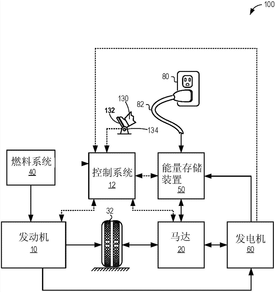
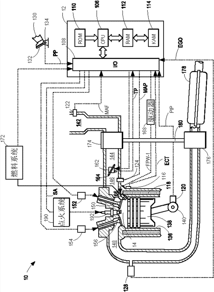
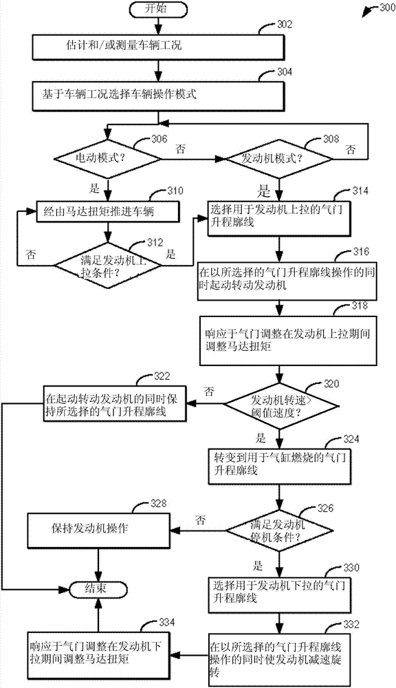
[0016] The following description is concerned with reducing hybrid vehicle systems such as figure 1 A system and method for torque ripple that occurs during engine start and stop events in a vehicle system for the vehicle. The vehicle system may include an engine configured with variable valve lift actuation, as referenced figure 2 The engine system described. The controller can be configured to execute a control program (such as image 3 example routine) to reduce engine compression pressure during engine pull-up and pull-down events, thereby reducing associated pumping losses, torque ripple, and NVH. An example valve lift profile reference that can be used by the controller to reduce cylinder Figure 4 shown. refer to Figure 5 Example valve lift adjustments during vehicle operation are shown. In this way, engine restart and shutdown torque ripple is reduced.

[0017] figure 1 An example vehicle propulsion system 100 is shown. Vehicle propulsion system 100 includes...


PUM


Abstract

The application relates to methods and systems for torque control. Methods and systems are provided for reducing torque pulsations during hybrid engine shutdown and restarts. A valve actuating mechanism may be actuated to operate an engine with a selected valve lift profile during engine restart and shutdown events that is distinct from the valve lift profile applied during cylinder combustion. The selected valve lift profile reduces cylinder pressure during engine shutdown and restarts.

Description

technical field [0001] The present description generally relates to methods and systems for controlling valve lift profiles to reduce torque pulsations during engine cranking and shutdown. Background technique [0002] Vehicles have been developed to perform an engine stop under idle conditions when certain conditions are met, and then automatically restart the engine when restart conditions are met (also referred to as a start / stop system). This idle stop system can save fuel, reduce exhaust emissions, reduce vehicle noise, etc. Similarly, hybrid electric vehicle systems operate the vehicle via the engine under selected conditions and operate the vehicle via the electric motor under other conditions. The reduction in engine operating time can result in significant fuel savings. [0003] However, in such vehicle systems, large torque ripples are experienced during engine restarts when the engine is cranking, and during engine shutdown when the engine is spinning to a stand...

Claims


Application Information

Patent Timeline
Patent Type & Authority Applications(China)
IPC IPC(8): F01L13/00F01L13/08F02D13/02F02D13/08F02N11/08
CPCB60W10/06B60W20/00F02D13/0207F02D29/02F02D41/042F02D41/062F02D2013/0292F02D2041/001F02D2200/101F02D2200/503F02N11/0814F02N19/004Y02T10/12Y10S903/905B60K6/24B60W20/20B60Y2200/92B60Y2300/192B60Y2300/205B60Y2300/437B60W20/15
Inventor T·G·莱昂内K·J·米勒
Owner FORD GLOBAL TECH LLC
Why Eureka
Try Eureka