
Limit short shaft hydraulic motor core pulling method
A technology of hydraulic motors and short shafts, which is applied in the manufacture of motor generators, electrical components, electromechanical devices, etc. It can solve the problems of lack of available places for motor pumping (piercing) cores, failure to meet the requirements for core threading and hoisting, and small workshop space. , to achieve the effect of ensuring construction safety, simple and convenient working process, and reducing labor intensity
- Summary
- Abstract
- Description
- Claims
- Application Information
AI Technical Summary
Problems solved by technology
Method used
Image

Examples
Embodiment 1
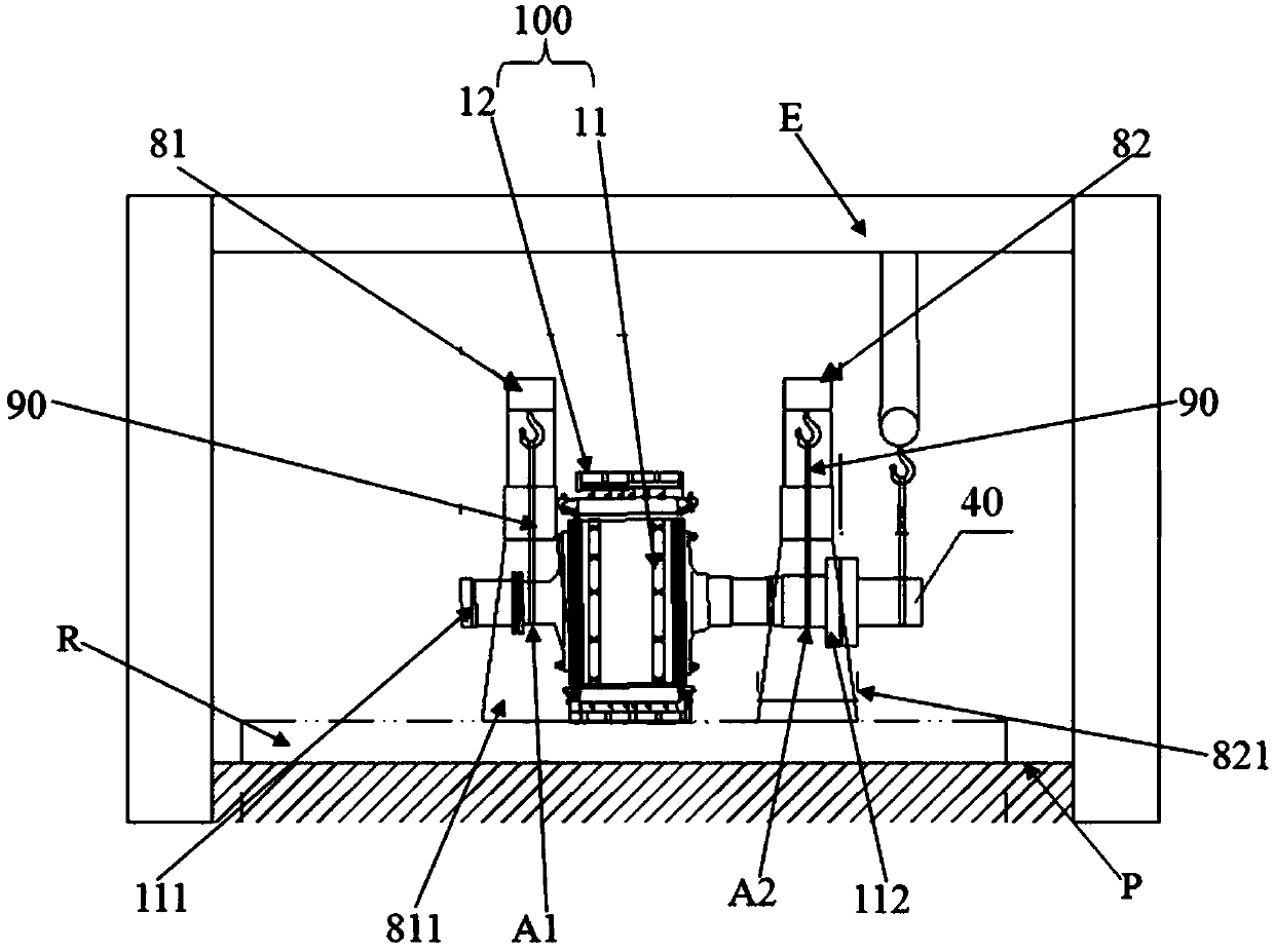
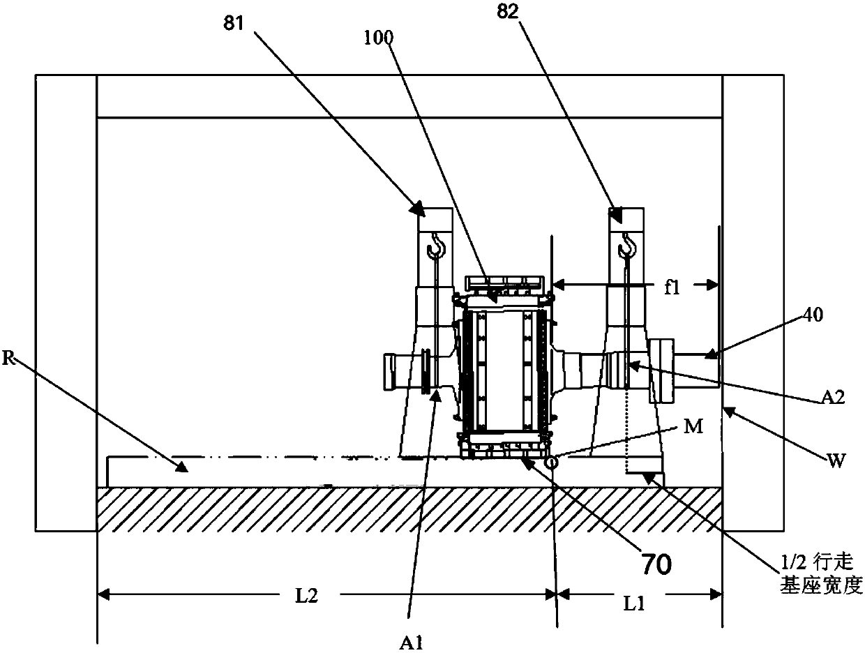
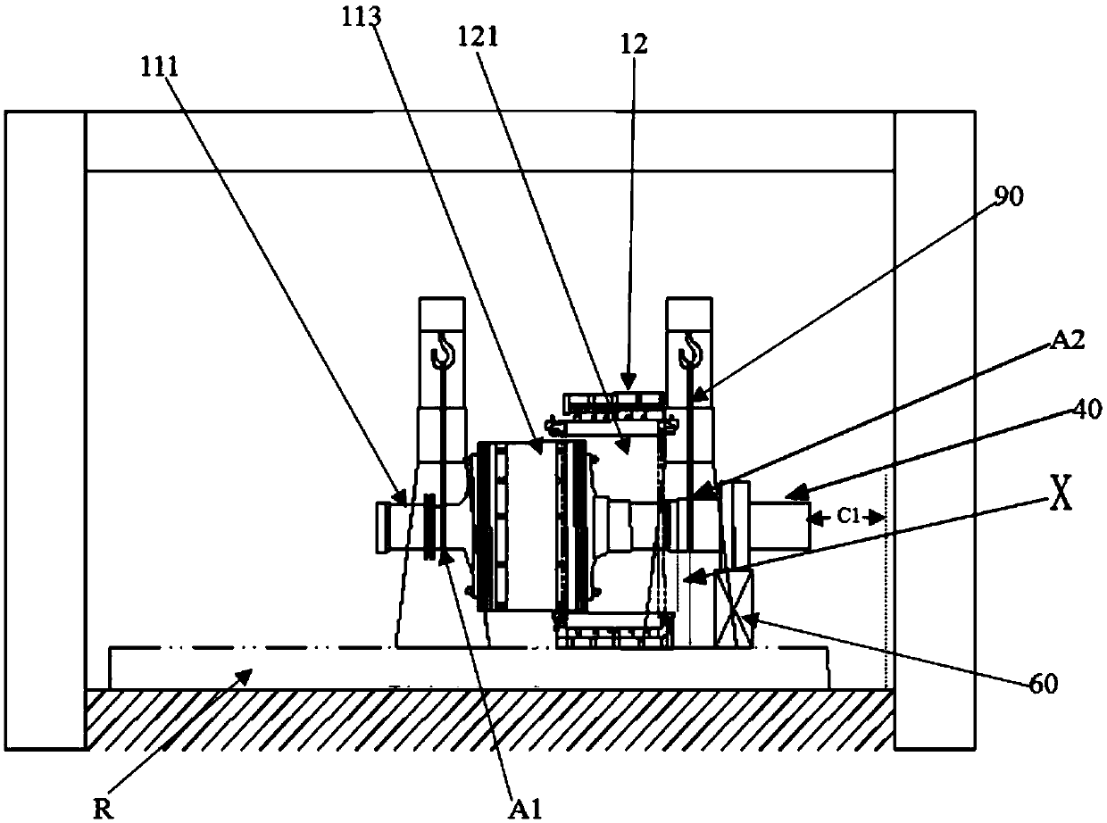
[0058] A preferred embodiment of the present invention the ultimate short-axis hydraulic motor core threading method, see Figure 1-Figure 6 , which basically includes the following steps:
[0059] (1) Short shaft installation preparation: insert a buffer isolation plate (not shown) in the inner hole 121 of the stator 12 of the motor 100, so that the buffer isolation plate is interposed between the stator 12 and the rotor 11, preventing the rotor 11 from The inner hole 121 of the stator 12 is in direct contact with the hole wall; the two hoisting ropes 90 are respectively sleeved on the two hoisting points of the rotating shaft 1111 of the rotor 11, one hoisting point A1 is close to the motor collector ring 111, and the other hoisting point A2 is close to the rotor. The coupling 112 side is defined as the coupling side lifting point; the rotor 11 and the stator 12 are integrally lifted to a core pulling site P by using a hydraulic gantry crane.
[0060] Specifically as figur...
Embodiment 2
[0078] Embodiment 2 is completely consistent with Embodiment 1 in the core pulling step. The only difference is that the short shaft installation preparation, short shaft installation, limit point selection, and overall lifting to the limit point in Embodiment 1 are changed to "limit point selection, overall lifting to the limit point, and short shaft installation" steps. This is because the selection of the limit point does not necessarily have to be carried out after the installation of the short shaft is completed. After the short shaft 40 of a certain specification and length is selected, it can be based on the actual situation of the core-pulling site. Just find the limit point M, and then directly hoist the motor 100 as a whole to the position of the limit point M, then connect the short shaft 40 to the shaft coupling 112 of the rotating shaft, and then perform the operation of the core pulling step. It is understandable that such a scheme is also feasible. This soluti...
PUM
| Property | Measurement | Unit |
|---|---|---|
| Thickness | aaaaa | aaaaa |
Abstract
Description
Claims
Application Information