Two-stage single-phase inverter

A single-phase inverter and single-phase technology, applied in the inverter field, can solve the problems of expensive power devices, lower system reliability, complex quantity structure, etc., and achieve the effects of low cost, small leakage current and good safety

Pending Publication Date: 2018-01-30
胡炎申
View PDF0 Cites 5 Cited by
  • Summary
  • Abstract
  • Description
  • Claims
  • Application Information

AI Technical Summary

Problems solved by technology

Under this working condition, all power switching devices work at full power rating, because the power devices are expensive, have a large number and complex structure, and at the same time, it is difficult to implement the control strategy, which increases the cost of circuits and devices, reduces system reliability, increased switching power consumption

Method used


Image

  • Two-stage single-phase inverter
  • Two-stage single-phase inverter
  • Two-stage single-phase inverter

Examples


Embodiment Construction

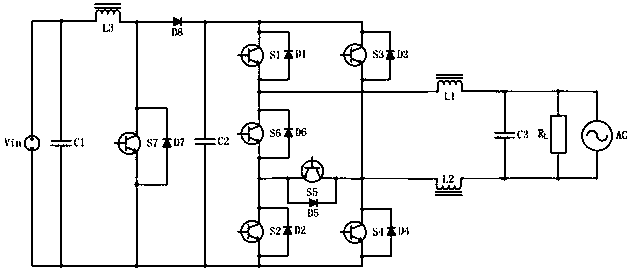
[0027] The circuit principle of the two-stage time-division multiplexing single-phase multi-level inverter in Embodiment 1 of the present invention is as follows Figure 3 to Figure 8 shown in image 3 In the schematic diagram of the two-stage time-division multiplexing single-phase multi-level inverter and its control strategy shown, the inverter is composed of a front-stage DC-DC boost circuit combined with a rear-stage single-phase multi-level inverter circuit.

[0028] After the DC input power Vin is filtered by the DC filter capacitor C1, it is supplied to the DC-DC boost circuit with a stable DC input to obtain a high voltage on the DC bus capacitor C2, and then passes through the single-phase multi-level inverter circuit to obtain a high-frequency square Wave, and finally by the output filter inductors L1, L2 and capacitor C3 AC high-frequency filter to obtain a sine wave output.

[0029] The control circuit of this inverter includes a controller, and the controller in...


PUM


Abstract

The invention discloses a two-stage single-phase inverter, including a DC input power supply, a DC-DC booster circuit, a single-phase multi-level inverter circuit and a control circuit. The input endof the DC-DC booster circuit is connected with the DC input power supply, and the output end is connected with the input end of the single-phase multi-level inverter circuit; when a voltage of the DCinput power supply is lower than a voltage peak of AC output of the single-phase multi-level inverter circuit, the two-stage single-phase inverter works in a Boost mode, the DC-DC booster circuit works in an SPWM high-frequency switch state, and the single-phase multi-level inverter circuit works in a power frequency commutation state; and when the voltage of the DC input power supply is higher than the voltage peak of AC output of the single-phase multi-level inverter circuit, the two-stage single-phase inverter works in a Buck mode, the DC-DC booster circuit works in a bypass working state,and the single-phase multi-level inverter circuit works in an SPWM high-frequency switch state. The front stage and the rear stage of the two-stage single-phase inverter work in a partial-power mode,a relatively small DC bus capacitor can be used, and switch power consumption is small.

Description

technical field] [0001] The invention relates to inverter technology, in particular to a two-stage single-phase inverter. Background technique] [0002] Inverter is one of the key technologies in the field of power electronics. Traditional single-phase inverters such as figure 1 As shown, it includes power switch tubes S1, S2, S3, and S4. The DC input side is connected with a filter capacitor Cin. According to the switching action of the power switch device, a series of AC square wave voltages are output. The maximum square wave amplitude is limited to the DC input voltage . The inverter forms two groups of linked power switches with diagonal lines S1 and S4, and diagonal lines S2 and S3. The two groups of power switches are turned on alternately. As a result, positive and negative square wave voltages are output on the AC side, and then through The AC filter circuit composed of L1, L2 and Cout outputs a sine wave voltage. According to the specific switching sequence sele...

Claims


Application Information

Patent Timeline
Patent Type & Authority Applications(China)
IPC IPC(8): H02M7/483
Inventor 胡炎申
Owner 胡炎申
Why Eureka
Try Eureka