Ethernet exchange function implementation system and Ethernet exchange function implementation method based on domestic FPGA (field programmable gate array)

A switching function, Ethernet technology, applied in transmission systems, digital transmission systems, data switching networks, etc., can solve the problem that fixed-function switching chips are difficult to meet, lack flexibility, high scalability design modules, and Ethernet switching technology is complex to achieve problems, such as convenience and flexible business processing, rich functions, and flexible hardware and software solutions

Active Publication Date: 2018-02-13
GUANGZHOU HAIGE COMM GRP INC
View PDF7 Cites 26 Cited by
  • Summary
  • Abstract
  • Description
  • Claims
  • Application Information

AI Technical Summary

Problems solved by technology

[0004] Due to the complexity of the implementation of Ethernet switching technology, real devices can only provide functions for a specific use mode, and the use of dedicated Ethernet switching chips to realize network switching business processing lacks more flexible and adaptable to various Purpose-built and highly scalable design modules
At the same time, due to the rapid evolution of protocols for networking functions, especially the development of SDN (Software Defined Networking) technology, it is difficult for fixed-function switching chips to meet the requirements of continuous development in the future.

Method used


Image

  • Ethernet exchange function implementation system and Ethernet exchange function implementation method based on domestic FPGA (field programmable gate array)
  • Ethernet exchange function implementation system and Ethernet exchange function implementation method based on domestic FPGA (field programmable gate array)
  • Ethernet exchange function implementation system and Ethernet exchange function implementation method based on domestic FPGA (field programmable gate array)

Examples


Embodiment

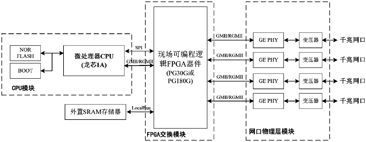
[0064] Such as figure 1 As shown, the realization hardware of Ethernet switching service processing in the communication chassis equipment consists of front-end physical circuit (PHY), field programmable logic FPGA device, external SRAM memory and microprocessor (or CPU) device. The front-end physical circuit of the network port is a standard circuit of the Ethernet interface, which is composed of an isolation transformer and a dedicated Ethernet PHY chip (GEPHY). The Ethernet PHY chip here can be BCM5464 or 88E1111. The field programmable logic FPGA device completes the buffering of the MAC of the network port and the layer-2 / layer-3 forwarding processing of the network packet, and the domestically produced PG30 chip and PG180 chip can be used. The external SRAM is used for temporarily storing and forwarding network packets, and a general-purpose SRAM chip can be used. The microprocessor realizes the configuration and status query function of the internal register space of t...


PUM


Abstract

The invention discloses an Ethernet exchange function implementation system and an Ethernet exchange function implementation method based on a domestic FPGA (field programmable gate array). The Ethernet exchange function implementation system comprises an Ethernet port physical layer module, an FPGA device, a microprocessor and an external SRAM which are in sequential connection, wherein the Ethernet port physical layer module is used for being connected with an Ethernet port, processing data of an Ethernet port physical layer and transmitting the data to the FPGA device; the FPGA device is used for completing buffering of Ethernet port MAC as well as a layer-2 / layer-3 forwarding processing process; the microprocessor is used for implementing configuration of an internal memory space of the FPGA and a status inquiry function and processing Ethernet data packets; the external SRAM is used for temporary storage of forwarded network packets. The Ethernet exchange function implementation system has the advantage that a corresponding register of the FPGA is configured through software to achieve Ethernet exchange and CPU software is provided for processing an Ethernet data interface, sothat commonly used Ethernet exchange business processing can be supported flexibly and conveniently.

Description

technical field [0001] The invention relates to the technical field of electronic information communication, in particular to a domestic FPGA-based system and method for realizing Ethernet switching functions. Background technique [0002] The specification of the physical / electrical characteristics of the Ethernet interface conforms to the 802.3 protocol, and it is a standard communication interface commonly used in the world at present. The commonly used Ethernet interface in the chassis of communication equipment is 1000Base-T at a gigabit rate, and its physical rate is 1000 Mbps. As an implementation of the physical layer in the OSI seven-layer protocol, the Ethernet interface has been widely used. [0003] MAC is Media Access Control, which is the sub-layer protocol of media access control. This protocol is located in the lower half of the data link layer in the OSI seven-layer protocol, and is mainly responsible for controlling and connecting the physical medium of th...

Claims


Application Information

Patent Timeline
IPC IPC(8): H04L12/931H04L12/933
CPCH04L49/10H04L49/351H04L49/40
Inventor胡国浩伍思廉李牧马超
OwnerGUANGZHOU HAIGE COMM GRP INC