Electric stirrer

An electric stirrer and stirring shaft technology, which can be applied in the directions of mixer accessories, mixers with rotating stirring devices, chemical instruments and methods, etc., can solve problems such as falling into

Inactive Publication Date: 2018-04-06
河南大松仪器设备有限公司
View PDF0 Cites 1 Cited by
  • Summary
  • Abstract
  • Description
  • Claims
  • Application Information

AI Technical Summary

Problems solved by technology

[0003] Aiming at the personal safety of laboratory personnel caused by the splashing of the above-mentioned reactants and the pollutants falling into the reactants, the present invention provides an electric stirrer. The electric stirrer of the present invention is provided with a protective cover, which can prevent the reactants from collapsing. Splashing, while also preventing contaminants from contaminating the reactants

Method used


Image

  • Electric stirrer
  • Electric stirrer
  • Electric stirrer

Examples


Embodiment 1

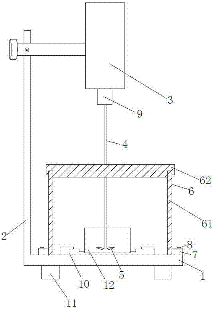
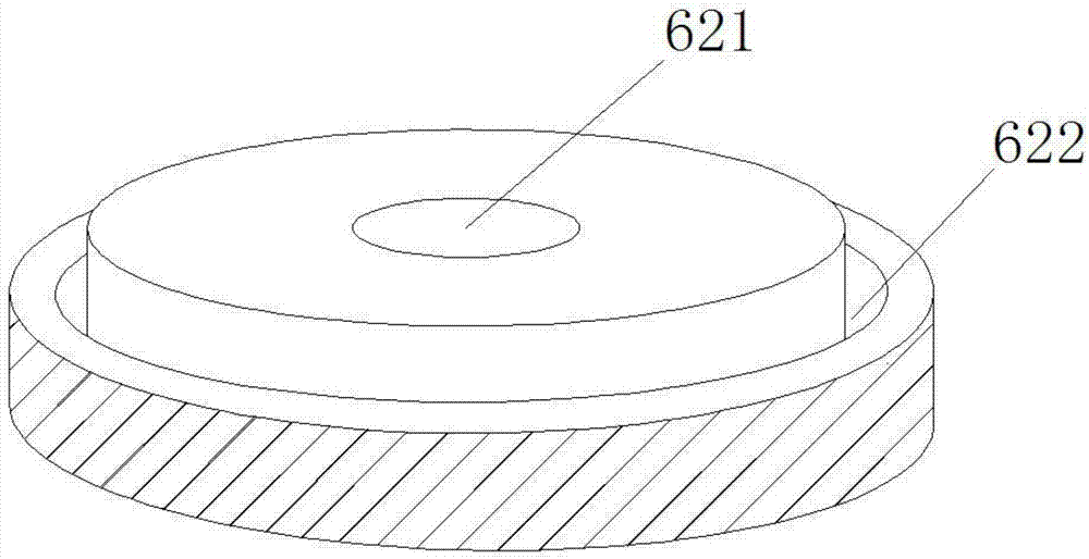
[0026] Such as figure 1 , figure 2 , image 3 As shown, an electric mixer includes a base 1, a support 2 is provided on the base 1, a motor 3 is provided on the top of the support 2, and the motor 3 is detachably connected with the stirring shaft 4, and the stirring shaft 4 Connected with the stirring paddle 5, the electric agitator also includes a protective cover 6, the protective cover 6 includes a protective cover body 61 and a protective cover 62, the protective cover body 61 is placed on the base 1, and the protective cover The upper part of the body 61 is provided with an opening 611, and the protective cover 62 is provided with a through hole 621 that allows the stirring shaft to pass through. The through hole 621 is in clearance fit with the stirring shaft 4, and the bottom of the protective cover 62 is provided with an annular groove. 622 , the annular groove 622 cooperates with the opening 611 .

[0027] The electric stirring shaft of the present invention is pr...

Embodiment 2

[0029] Based on Example 1, such as figure 1 As shown, the protective cover body 61 is provided with a protrusion 7, and the protrusion 7 is provided with a bolt 8, and the base 1 is provided with a bolt hole matched with the bolt. The protective cover body 61 is provided with a bolt 8, and the base 1 is provided with a bolt hole, so that the protective cover body 61 and the base 1 are connected by bolts, so that the protective cover body 61 is conveniently dismounted from the base 1, and the protective cover body 61 can be conveniently protected. Cleaning of the cover body 61, while in use, the protective cover body 61 can be fixed on the base 1 to prevent stirring and vibration or the experimenter from accidentally touching the protective cover 6 to cause the protective cover 6 to shift and affect the stirring.

Embodiment 3

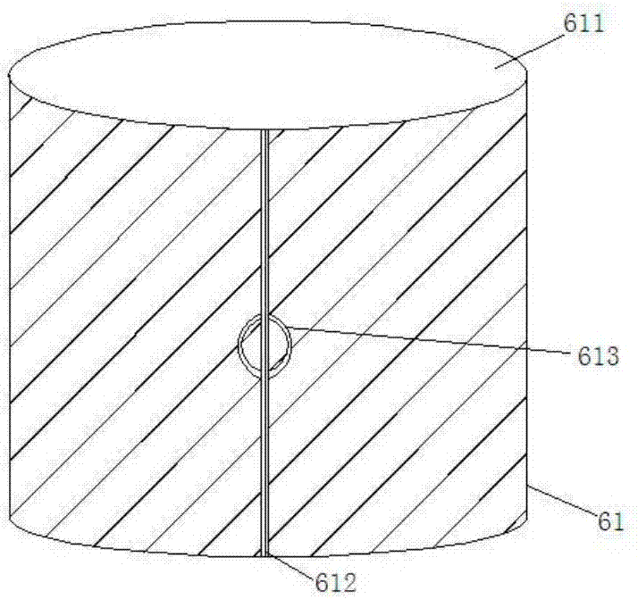
[0031] Based on Example 1, such as figure 2 As shown, the protective cover body 1 is provided with a sliding door 612 , and the sliding door 612 is provided with a handle 613 . A sliding door 612 is provided on the protective cover body 61 , and a handle 613 is provided on the sliding door 612 to facilitate experimenters to put the container 12 containing the reactant into the protective cover 6 .


PUM


Abstract

The invention discloses an electric stirrer which comprises a base, wherein a bracket is arranged on the base; a motor is arranged on the top of the bracket and detachably connected with a stirring shaft; the stirring shaft is connected with a stirring paddle; the electric stirrer further comprises a protecting hood; the protecting hood comprises a protecting hood body and a protective cover; theprotecting hood body is arranged on the base; an opening is formed in the upper part of the protecting hood body; a through hole allowing the stirring shaft to penetrate is formed in the protective cover; the through hole is in clearance fit with the stirring shaft; and an annular groove is formed in the bottom of the protective cover and matched with the opening. The electric stirrer disclosed bythe invention is provided with the protective cover, so that the condition that reactants in the protecting hood splash to threaten safety of laboratory personnel or pollutants drop into the reactants to pollute the reactants can be avoided.

Description

technical field [0001] The invention relates to the field of experimental equipment, in particular to an electric stirrer. Background technique [0002] Electric mixer is one of the commonly used equipment in the laboratory. It is mainly used to mix materials and prevent material from settling. It has the characteristics of small size and convenient use. However, during the operation of the experiment, some chemical reactions will be accompanied by strong reaction phenomena or the splashing of the reactants caused by too fast stirring will pose a threat to the personal safety of the experimenters, and if no measures are taken for long-term stirring, dust Such pollutants fall into the reactants, causing contamination of the reactants; at the same time, the containers containing the reactants in the laboratory are generally made of glass and are relatively fragile. The vibration generated when the reactants are stirred will cause the containers to shift, resulting in stirring ...

Claims


Application Information

Patent Timeline
Patent Type & Authority Applications(China)
IPC IPC(8): B01F7/18B01F15/00
CPCB01F27/90B01F35/45B01F35/43
Inventor 刘真
Owner 河南大松仪器设备有限公司
Why Eureka
Try Eureka