Device for installing deep-water high-lift submersible sewage pump

A sewage pump and high-lift technology, which is applied to parts, pumps, and pump components of pumping devices used for elastic fluids, and can solve problems such as inability to play a limiting role, failure to use normally, and structural damage to the installation system

Pending Publication Date: 2018-04-13
LANSHEN GRP CORP LTD
View PDF6 Cites 0 Cited by
  • Summary
  • Abstract
  • Description
  • Claims
  • Application Information

AI Technical Summary

Problems solved by technology

The installation device has the following problems: (1) Due to the large gap between the matching part of the bracket and the guide rod in the existing installation method, the deep-water high-lift submersible sewage pump has a long stroke during lifting. Prone to lame card and poor movement
Due to the limited rigidity of the guide rod in the existing installation method, it is easy to produce bending deformation under the action of the huge external force formed by the recoil and cannot play a due role in limiting the position of the deep-water high-lift submersible sewage pump; in addition, the existing The guide rod in the installation method is cylindrical, and there is a large gap between the parts matched with the bracket, which also cannot play the proper limit function
Eventually, the pump body will rotate relative to the radial direction of the guide rod, and then there will be structural damage to the installation system, leakage and other problems that cannot be used normally.

Method used


Image

  • Device for installing deep-water high-lift submersible sewage pump
  • Device for installing deep-water high-lift submersible sewage pump
  • Device for installing deep-water high-lift submersible sewage pump

Examples


Embodiment Construction

[0022] The technical solution of the present invention will be described in detail below in conjunction with the accompanying drawings.

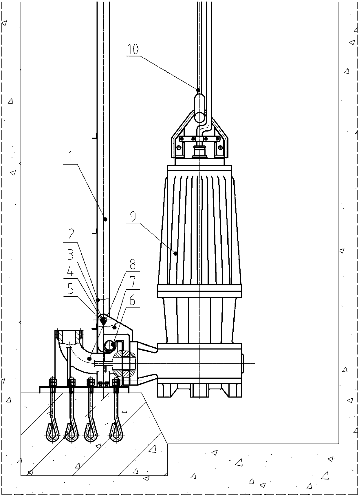
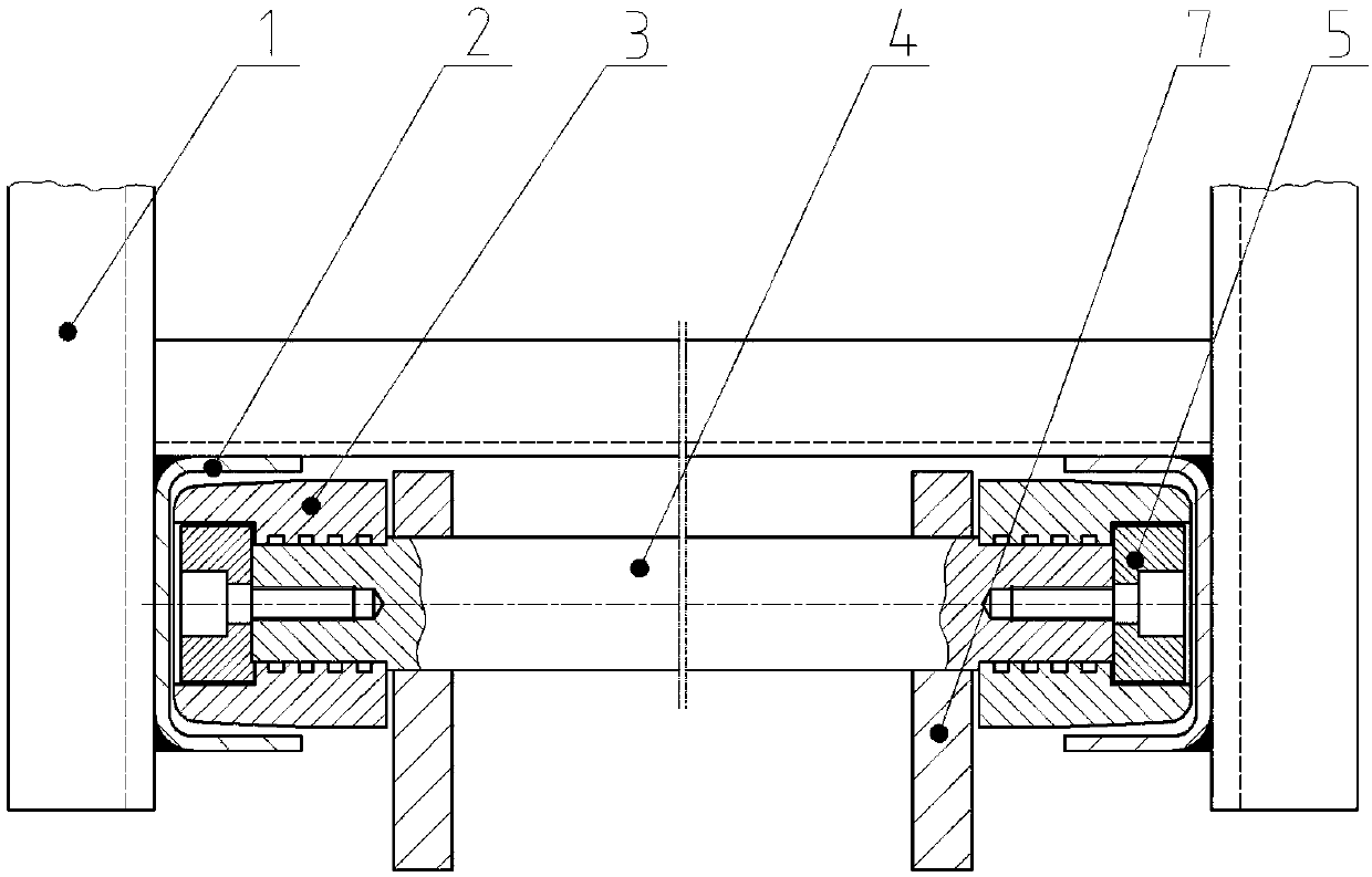
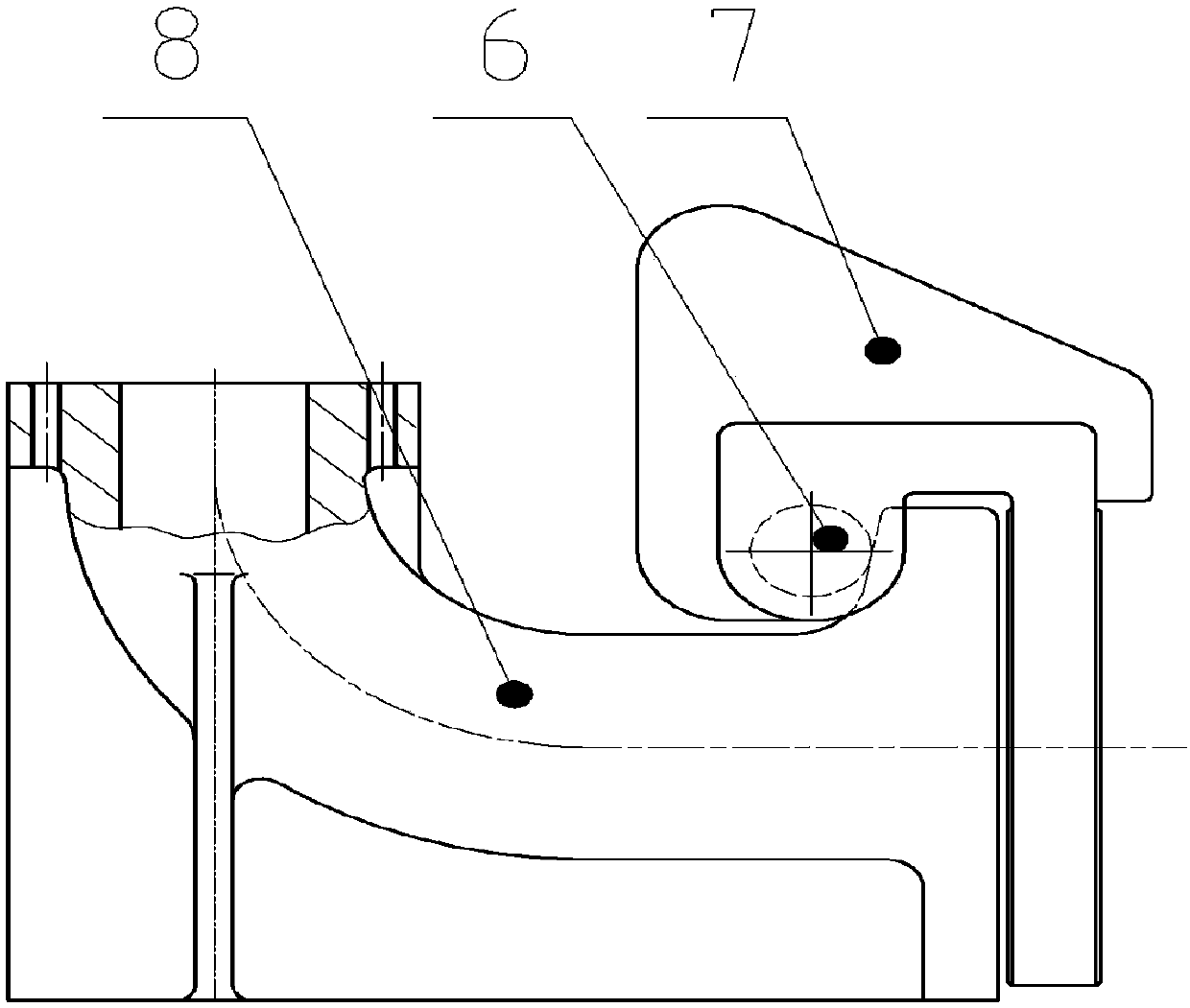
[0023] Such as Figure 1 to Figure 7 As shown, a device for installing a deep-water high-lift submersible sewage pump according to an embodiment of the present invention includes a guide rail 1 including a rail 2 , a roller 3 , a guide shaft 4 , a bracket 7 and a base 8 . The bottom end of the guide rail 1 is fixedly connected to the base 8 . There are two rails 2, and the two rails 2 are arranged oppositely. The roller 3 is located in the track 2, the roller 3 can move up and down along the track 2, and the gap between the roller 3 and the single side wall of the track 2 is less than 1mm. The guide shaft 4 is connected between the rollers 3 . The bracket 7 is fixedly connected with the guide shaft 4 .

[0024] When using the device with the above-mentioned structure to install the deep-water high-lift submersible sewage pump 9 , the dee...


PUM


Abstract

The invention discloses a device for installing a deep-water high-lift submersible sewage pump. The device comprises guide rails containing tracks, rolling wheels, a guiding shaft, a support and a base, wherein the bottom ends of the guide rails are fixedly connected onto the base; the two tracks are arranged oppositely; the rolling wheels are located in the tracks and can move up and down along the tracks; a clearance between each rolling wheel and a unilateral wall face of the corresponding track is smaller than 1mm; the guiding shaft is connected between the rolling wheels; and the supportis fixedly connected with the guiding shaft. According to the device for installing the deep-water high-lift submersible sewage pump provided by the invention, through the tracks arranged in the guiderails, an accurate guiding effect can be achieved during a lifting process when the deep-water high-lift submersible sewage pump is installed and overhauled, and the deep-water high-lift submersiblesewage pump is ensured to freely lift within a longer travel range; and meanwhile, a limiting effect can be achieved on a rigid body formed by the support and the deep-water high-lift submersible sewage pump, so that the deep-water high-lift submersible sewage pump is ensured to keep stable under the situation that back flushing is formed due to hydraulic impact during operation, and the occurrence of the phenomenon that the deep-water high-lift submersible sewage pump rotates around a positioning shaft is effectively avoided.

Description

technical field [0001] The invention belongs to the technical field of mechanical manufacturing and installation, and in particular relates to a device for installing a deep-water high-lift submersible sewage pump. Background technique [0002] The existing submersible sewage pump installation device is only suitable for the installation of the submersible sewage pump under relatively shallow water level conditions. The installation device has the following problems: (1) Due to the large gap between the matching part of the bracket and the guide rod in the existing installation method, the deep-water high-lift submersible sewage pump has a long stroke during lifting. It is prone to problems of lame card and poor movement. (2) The deep-water high-lift submersible sewage pump is always subjected to huge hydraulic impact during operation, resulting in recoil. Due to the limited rigidity of the guide rod in the existing installation method, it is easy to produce bending deform...

Claims


Application Information

Patent Timeline
Patent Type & Authority Applications(China)
IPC IPC(8): F04D7/00F04D29/00
CPCF04D7/00F04D29/007
Inventor 王震颜岩陈斌董绵杰黄学军史长彪李善庭张允敬徐啸
Owner LANSHEN GRP CORP LTD
Why Eureka
Try Eureka