
A test method for inductance packaging based on inductance packaging testing equipment
A technology of testing equipment and testing methods, applied in packaging, packaging protection, transportation and packaging, etc., can solve the problems of unreasonable layout, difficult to discharge defective products, and low pass rate.
- Summary
- Abstract
- Description
- Claims
- Application Information
AI Technical Summary
Problems solved by technology
Method used
Image

Examples
Embodiment
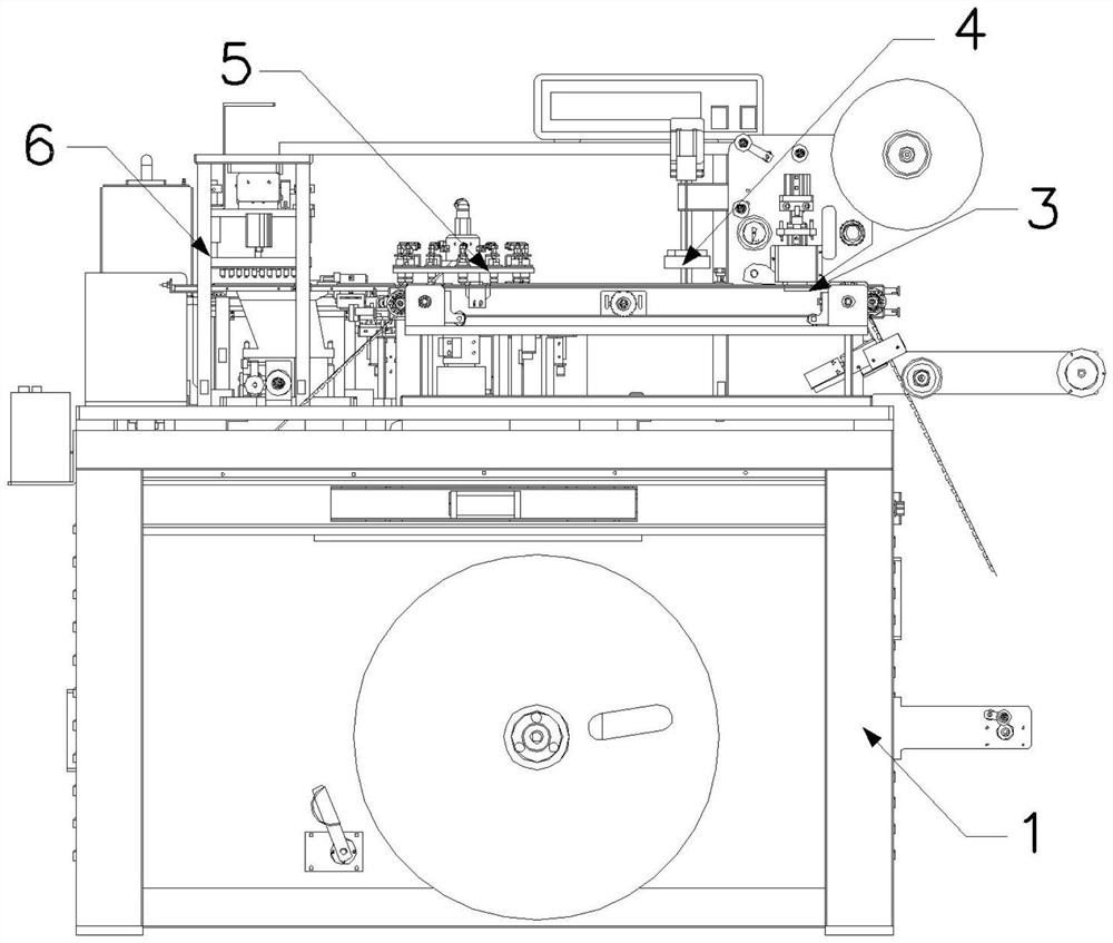
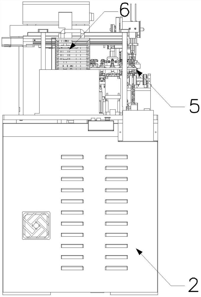
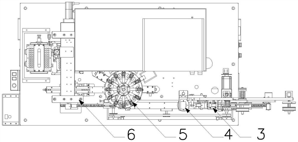
[0055] Example: such as Figure 1-28As shown, the present invention provides a kind of inductance packaging test equipment, comprises frame 1, electrical cabinet 2, packaging mechanism 3, CCD detection mechanism 4, testing mechanism 5 and loading mechanism 6, and electrical cabinet 2 is arranged on the side of frame 1 , the top surface of the frame 1 is provided with an operation panel; the packaging mechanism 3 and the CCD detection mechanism 4 are fixed on the mounting panel of the frame 1 by the bolts at the bottom of the delivery bracket 17, and one end of the delivery bracket 17 is provided with a take-up roller 9, and the take-up roller The roller 9 is fixed on the panel by the fixed shaft 8, and the carrier tape 10 is wound and arranged on the surface of the take-up roller 9, and the carrier tape 10 is connected with the take-up reel 35 after passing through the surface of the transition wheel 11 and the pressure roller 31, and the take-up reel 35 The center is connecte...
PUM
 Abstract
Description
Claims
Application Information