AI technical title is built by Patsnap AI team. It summarizes the technical point description of the patent document.
A compressor and barrel-type technology, applied in the field of refrigerant compressors, can solve the problems of single-layer layout of the unit, failure to meet high-pressure sealing, and heavy unit weight, etc., to achieve shortened procurement cycle, light weight, and low cost input Effect
Active Publication Date: 2019-04-26
SHENYANG TURBO MASCH CORP
View PDF7 Cites 0 Cited by
Summary
Abstract
Description
Claims
Application Information
AI Technical Summary
This helps you quickly interpret patents by identifying the three key elements:
Problems solved by technology
Method used
Benefits of technology
Problems solved by technology
MCL horizontally split refrigerant compressors have the advantages of light weight and low cost of the unit, but they cannot meet the requirements of high-pressure sealing and difficult to achieve single-layer arrangement of units; while BCL vertically split refrigerant compressors have good high-pressure sealing , A single-layer layout of the unit can be realized, but there are problems of heavy unit weight and high cost
Method used
Image
Click on the blue label to locate the original text in one second.
Reading with bidirectional positioning of images and text.
Examples
Embodiment 1
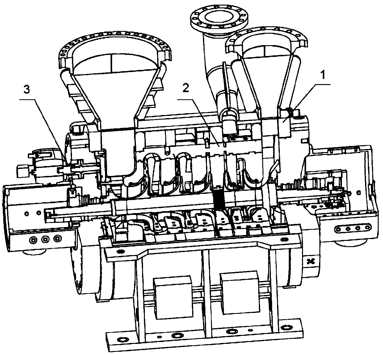
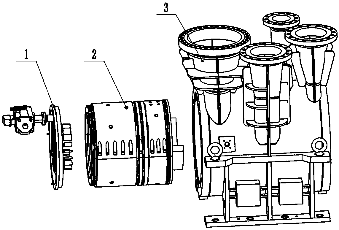
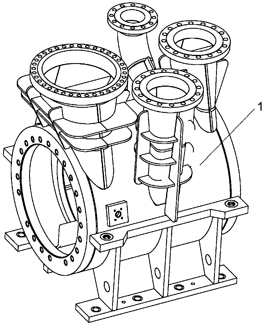
[0035] Such as Figures 1 to 4 As shown, the cylindrical refrigerant compressor includes a cylindrical welded casing 1, an inner casing 2 and an adjustable guide vane actuator 3. A support ring and a baffle are welded on the inner wall of the cylindrical welded casing 1, and the support ring And the baffle forms a volute inside the cylindrical welding casing 1, the inner casing 2 is arranged inside the cylindrical welding casing 1, and a connecting rib group is arranged along the circumferential direction of the shell wall of the inner casing 2, and the connecting ribs The group is used to divide the inner casing 2 into at least two unit inner casings; the adjustable guide vane actuator 3 is arranged in the cylindrical welding casing 1 on the side close to the inner casing 2 .
[0036] The cylindrical welded casing 1 is welded by the Q345R plate, and the Q345R plate is composed of the following chemical composition in weight percentage: C 0.02%, Si 0.3%, Mn 1.2%, P 0.002%, S 0...
Embodiment 2
[0044]Referring to Example 1, the cylindrical refrigerant compressor provided in this embodiment is different in that the cylindrical welded casing 1 is welded by the Q345R plate, and the Q345R plate consists of the following weight percentages: Chemical composition: C0.2%, Si 0.5%, Mn 1.3%, P 0.01%, S 0.01%, CaO 0.003%, Co 0.16%, Cu 0.03%, Alt 0.02%, V 0.01%, and the balance of Fe and unavoidable impurities.
Embodiment 3
[0046] Referring to Example 1, the cylindrical refrigerant compressor provided in this embodiment is different in that the cylindrical welded casing 1 is welded by the Q345R plate, and the Q345R plate consists of the following weight percentages: Chemical composition: C0.1%, Si 0.2%, Mn 1.6%, P 0.02%, S 0.013%, CaO 0.0025%, Ni 0.4%, Co 0.18%, Cu0.2%, Alt 0.01%, V 0.025%, And the balance of Fe and unavoidable impurities.
PUM
Abstract
The invention relates to a cylindrical refrigerant compressor, comprising a cylindrical welded casing, an inner casing and an adjustable guide vane actuator, the cylindrical welded casing is provided with a volute inside; the inner casing is provided with Inside the cylindrical welded casing, a group of connecting ribs is provided along the circumferential direction of the casing wall of the inner casing, and the group of connecting ribs is used to divide the inner casing into at least two unit inner casings ; The inner casing is arranged in the cylindrical welding casing on one side close to the inner casing. The cylindrical refrigerant compressor provided by the invention not only has the advantages of light weight and low cost of the unit, but also satisfies the high-pressure tightness and difficult-to-achieve single-layer arrangement of the unit.
Description
technical field [0001] The invention relates to the technical field of refrigerant compressors, in particular to a cylindrical refrigerant compressor. Background technique [0002] At present, refrigerant compressors are mainly divided into two types, namely MCL horizontal split refrigerant compressors and BCL vertical split refrigerant compressors. MCL horizontally split refrigerant compressors have the advantages of light weight and low cost of the unit, but they cannot meet the requirements of high-pressure sealing and difficult to achieve single-layer arrangement of units; while BCL vertically split refrigerant compressors have good high-pressure sealing 1. The single-layer arrangement of the unit can be realized, but there are problems of heavy unit weight and high cost. Contents of the invention [0003] Aiming at the shortcomings of the above-mentioned prior art, the present invention provides a cylindrical refrigerant compressor. [0004] The purpose of the prese...
Claims
Application Information
Patent Timeline
Application Date:The date an application was filed.
Publication Date:The date a patent or application was officially published.
First Publication Date:The earliest publication date of a patent with the same application number.
Issue Date:Publication date of the patent grant document.
PCT Entry Date:The Entry date of PCT National Phase.
Estimated Expiry Date:The statutory expiry date of a patent right according to the Patent Law, and it is the longest term of protection that the patent right can achieve without the termination of the patent right due to other reasons(Term extension factor has been taken into account ).
Invalid Date:Actual expiry date is based on effective date or publication date of legal transaction data of invalid patent.

