Horizontal high-pressure heat exchanger applicable to cleaning medium evaporation

A technology for cleaning media and heat exchangers, which is applied in the direction of heat exchanger types, heat exchanger shells, indirect heat exchangers, etc. To achieve the effect of good high pressure sealing, eliminating thermal stress and reducing thermal stress

Inactive Publication Date: 2014-05-21
ZHEJIANG UNIV
View PDF6 Cites 0 Cited by
  • Summary
  • Abstract
  • Description
  • Claims
  • Application Information

AI Technical Summary

Problems solved by technology

[0003] Most of the existing horizontal heat exchangers with evaporation space adopt a single cylinder structure, which has high rigidity and insufficient flexibility, and will generate large thermal stress when the phase change temperature difference is large; this type of heat exchanger often adopts the bolt method The detachable connection of the flange has limited pressure bearing capacity, so it is not suitable for high pressure conditions
The tube bundle arrangement of the heat exchanger often adopts floating head type, U-shaped tube type or fixed tube sheet type. Among them, part of the tube side and shell side of the heat exchanger using the first two methods do not participate in heat exchange, and the heat transfer area is small; while the fixed tube sheet type The thermal stress of the heat exchanger is relatively large, so temperature compensating elements such as expansion joints must be installed, and the manufacturing process is complicated

Method used


Image

  • Horizontal high-pressure heat exchanger applicable to cleaning medium evaporation
  • Horizontal high-pressure heat exchanger applicable to cleaning medium evaporation
  • Horizontal high-pressure heat exchanger applicable to cleaning medium evaporation

Examples


Embodiment Construction

[0025] The present invention will be further described in detail below in conjunction with the drawings.

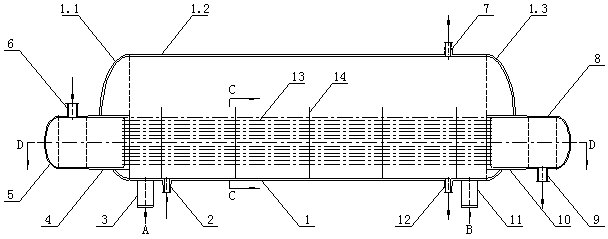
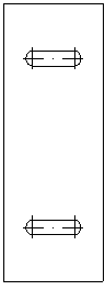
[0026] Such as figure 1 As shown, it includes a shell side composed of a shell 1, a baffle 14, a tube side composed of a left tube box 5, a right tube box 8, a left shaped tube plate 4, a right shaped tube plate 10, and a heat exchange tube bundle 13, and The sliding saddle 3 and the fixed saddle 11; the two sides of the lower part of the housing 1 are respectively installed with a left shaped tube plate 4 and a right shaped tube plate 10, the end faces of the extending cylinder of the left shaped tube plate 4 and the right shaped tube plate 10 are respectively Connected with the left tube box 5 and the right tube box 8. A row of baffles 14 are arranged evenly spaced between the left shaped tube plate 4 and the right shaped tube plate 10 in the housing 1, such as Figure 4 As shown, the baffle 14 is in the shape of a circle with a crown cut off, and the side of each baffle 14...


PUM


Abstract

The invention discloses a horizontal high-pressure heat exchanger applicable to cleaning medium evaporation. The horizontal high-pressure heat exchanger comprises a shell side, a tube side, a sliding saddle and a fixed saddle, wherein a left special-shaped tube plate and a right special-shaped tube plate are arranged on two sides of the lower portion of a shell and connected with a left tube tank and a right tube tank. Baffle plates are distributed between the left special-shaped tube plate and the right special-shaped tube plate at intervals evenly, and round crown removed sides of the baffle plates are positioned on the left side or the right side and arranged in a left and right alternative mode along the direction of the center axis. Two ends of a heat exchange tube bundle penetrate through the baffle plates to be connected onto the left special-shaped tube plate and the right special-shaped tube plate. A tube side hot medium inlet nozzle is arranged on the left tube tank, a tube side hot medium outlet nozzle is arranged on the right tube tank, a shell side material steam outlet tube is arranged on the shell, and a shell material inlet tube and a liquid discharging tube are arranged on two sides of the shell. By means of the horizontal high-pressure heat exchanger, space of the shell side and heat exchange area of the tube side are made full use of; thermal stress in occasions with high temperature difference is small; high-pressure sealing performance is good; by means of the combined supporting of the sliding saddle and the fixed saddle, a cylinder can perform telescopic motion in the axial direction, and thermal stress of the cylinder is reduced.

Description

Technical field [0001] The invention relates to a horizontal heat exchanger, in particular to a high-pressure horizontal heat exchanger suitable for the evaporation of a cleaning medium. Background technique [0002] In order to achieve efficient use of energy, industrial production often uses heat exchange to recover waste heat and waste heat, and use it to heat materials. In many cases, waste heat and waste heat can even be used to make the materials phase change and evaporate. This working condition requires the upper part of the heat exchanger Has a large evaporation space. [0003] Most of the existing horizontal heat exchangers with evaporation space adopt a single cylindrical structure, which has high rigidity and insufficient flexibility, and will generate large thermal stress when the phase transition temperature difference is large; this type of heat exchanger often uses the bolt method The blue detachable connection has limited pressure bearing capacity, so it is not ap...

Claims


Application Information

Patent Timeline
Patent Type & Authority Applications(China)
IPC IPC(8): F28D7/16F28F9/18F28F9/22
Inventor 刘宝庆郑毅骏金志江王曼曼张义堃
Owner ZHEJIANG UNIV
Why Eureka
Try Eureka