Process for making doped zinc oxide

a technology of indiumdoped zinc oxide and thin film, which is applied in the direction of metal/alloy conductors, coatings, conductors, etc., can solve the problems of poor subthreshold slope and high current, and achieve excellent field-effect electron mobilities and sufficient performance properties

Active Publication Date: 2009-03-26
EASTMAN KODAK CO
View PDF33 Cites 79 Cited by
  • Summary
  • Abstract
  • Description
  • Claims
  • Application Information

AI Technical Summary

Benefits of technology

[0055]It is an advantage of the present invention that it provides an advantageous process for atomic layer deposition of indium doped zinc-oxide-based thin film onto a substrate, well suited to a number of different types of substrates and deposition environments.
[0056]It is yet a further advantage of the present invention that it is adaptable for deposition on a web or other moving substrate, including deposition onto a large area substrate.
[0057]It is a further advantage of the present invention that it allows operation, in preferred embodiments, under atmospheric pressure conditions.
[0058]It is still a further advantage of the present invention that it can be employed in low temperature processes at atmospheric pressures, which processes may be practiced in an unsealed environment, open to ambient atmosphere.
[0059]The invention is also directed to a transistor comprising a zinc-oxide-based semiconductor, preferably on a flexible substrate, made by the present process.
[0060]Semiconductor films made by the present method are capable of exhibiting, in the film form, excellent field-effect electron mobilities of greater than 0.1 cm2 / Vs and on-off ratios of greater than 104, in which performance properties are sufficient for use in a variety of relevant technologies, including active matrix display backplanes.

Problems solved by technology
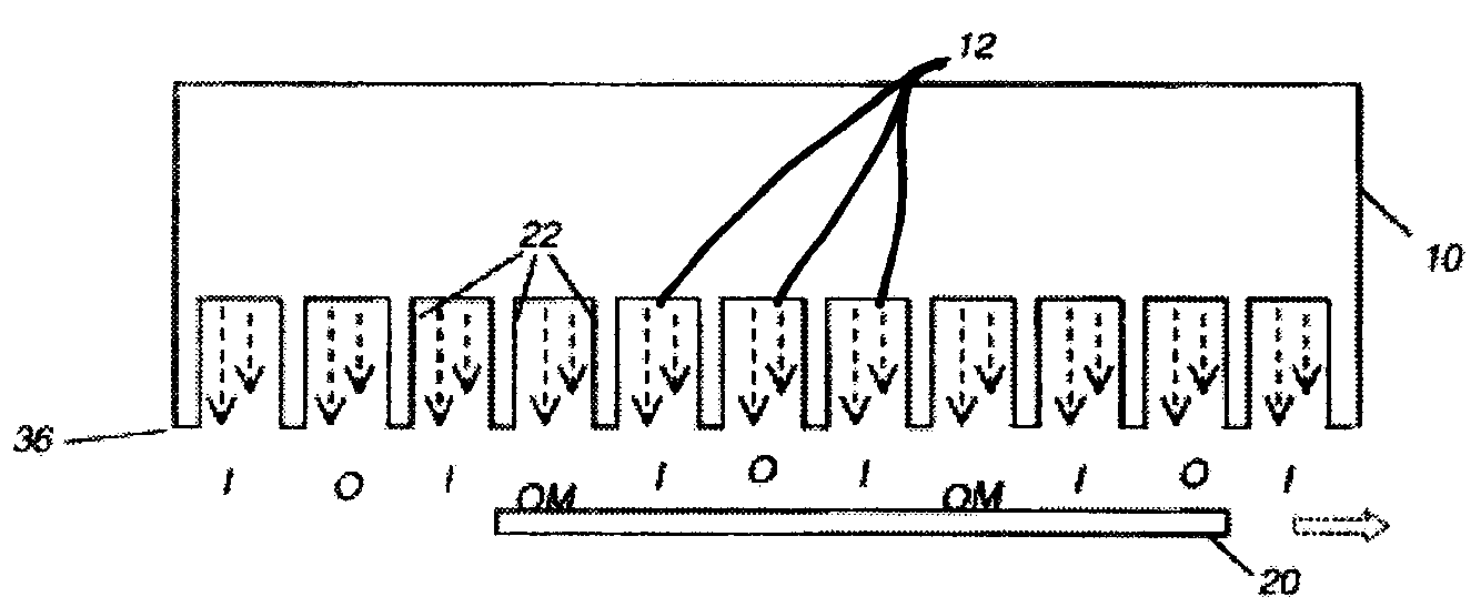
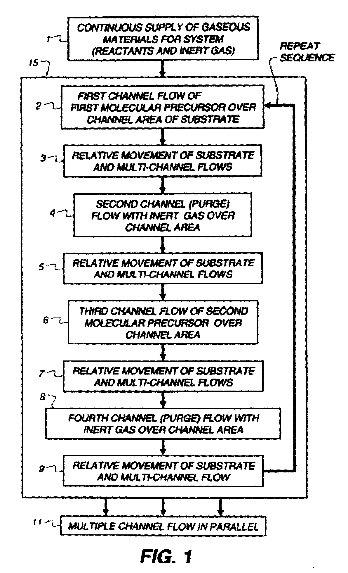
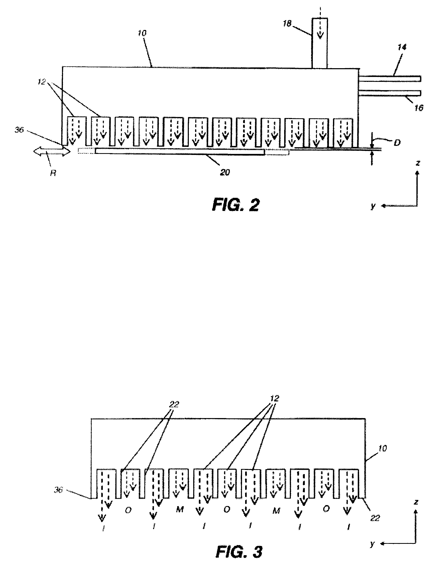
In the material produced by a spatial ALD process, defects in the materials may lead to two deleterious effects.
First, such materials may tend to have too high a concentration of native charge carrier, leading to high off currents.
Secondly, such materials may tend to contain defect sites that can cause bulk charging effects, leading to poor subthreshold slope.

Method used


Image

  • Process for making doped zinc oxide
  • Process for making doped zinc oxide
  • Process for making doped zinc oxide

Examples


example 1

[0219]This example demonstrates that indium oxide (In2O3 when alone) has been incorporated into the zinc oxide (ZnO when alone) semiconductor layer as an indium-zinc-oxide material. Samples prepared using the above apparatus were analyzed employing X-ray fluorescence spectroscopy on a purified, fused quartz substrate (GM electronics 63×63−040p). Table 1 below shows the flow rates of the zinc and indium precursors as well as the level of zinc and indium detected.

TABLE 1TrimethylDiethyl zincindium GasMolar FlowWeightGas FlowFlow Rate,Ratio, In / Zn,Zn DetectedIn DetectedRatioSampleRate, sccmsccmpercentage basis(μg / cm2)*(μg / cm2)**In / ZnComparative130083.70—1A1B132023%85.3None Detected—Less than 1.41C134046%66.46.60.101D138092%46.212.90.281E13160185%32.714.80.45*XRF measurement error (1σ) for Zn values is 0.3%**XRF measurement error (1σ) for In values is 1-2%

[0220]The data in Table 1 indicate that substantial amounts of In2O3 have been doped into the ZnO host using this experimental approa...

example 2

[0221]This example shows the change in crystallinity of the ZnO based semiconductor layer with increased incorporation of In2O3. X-ray diffraction was used to determine the relative crystallinity of the same coatings used in the previous Example 1. X-ray diffraction analysis is capable of determining if a material is non-crystalline (amorphous), since a perfectly amorphous material would generate no lattice peaks. In order to quantify the crystallinity of these InZnO samples, profile fitting summed the relative areas of the lattice peaks in each trace. The results are tabulated in Table 2 below. FIG. 26 is an overlaid plot of the X-ray diffraction spectra of the series in Table 2. It may easily be seen that the intensities of the peaks of the ZnO trace having zero doped In (Sample 1A) are drastically diminished in relative intensity and broadened as the In is introduced into the ZnO lattice at the highest level (Sample 1E), the latter of which is seen to be approaching a completely ...

example 5

[0229]This example describes the preparation of devices made using a range of In2O3 levels in the ZnO semiconductor layer. This experiment is similar to that described in Example 4 except that the flow rate of trimethylindium in bubbler 99 was varied from 0 to 160 sccm. The trimethylindium flow rates used varied as in Table 5.

TABLE 5TrimethylindiumAverageAverageFlow Rates, inMobility,ThresholdAverageSamplesccmcm2 / V * sVoltage, VIon / Ioff5A012.747.732 × 1095B2013.377.171 × 1095C4014.887.401 × 1095D8010.717.591 × 1095E1608.528.965 × 107

[0230]The data in Table 5 above show that as the trimethylindium flow rate is increased during the ZnO deposition that there is an increase in the mobilities up to a point (Sample 5C), and then there is a decrease in mobility at the highest trimethyl indium flow levels. On / off current ratios and average threshold voltages do not significantly shift within this series except at the highest trimethylindium flow rate.


PUM

PropertyMeasurementUnit
temperatureaaaaaaaaaa
weight ratioaaaaaaaaaa
speedaaaaaaaaaa

Abstract

The present invention relates to a process of making a zinc-oxide-based thin film semiconductor, for use in a transistor, comprising thin film deposition onto a substrate comprising providing a plurality of gaseous materials comprising first, second, and third gaseous materials, wherein the first gaseous material is a zinc-containing volatile material and the second gaseous material is reactive therewith such that when one of the first or second gaseous materials are on the surface of the substrate the other of the first or second gaseous materials will react to deposit a layer of material on the substrate, wherein the third gaseous material is inert and wherein a volatile indium-containing compound is introduced into the first reactive gaseous material or a supplemental gaseous material.

Description

CROSS-REFERENCE TO RELATED APPLICATIONS[0001]The present application is related to U.S. application Ser. No. 11 / 392,007, filed Mar. 29, 2006 by Levy and entitled, “PROCESS FOR ATOMIC LAYER DEPOSITION,” U.S. application Ser. No. 11 / 392,006, filed Mar. 29, 2006 by Levy and entitled “APPARATUS FOR ATOMIC LAYER DEPOSITION,” U.S. application Ser. No. 11 / 620,738, filed Jan. 8, 2007 by Levy and entitled “DELIVERY DEVICE FOR (DEPOSITION,” U.S. application Ser. No. 11 / 620,740, filed Jan. 8, 2007 by Nelson et al. and entitled “DELIVERY DEVICE COMPRISING GAS DIFFUSER FOR THIN FILM DEPOSITION,” U.S. application Ser. No. 11 / 620,744, filed Jan. 8, 2007 by Levy and entitled, “DEPOSITION SYSTEM AND METHOD USING A DELIVERY HEAD SEPARATED FROM A SUBSTRATE BY GAS PRESSURE,” U.S. application Ser. No. 11 / 627,525, filed Jan. 26, 2007 by Peter Cowdery-Corvan et al. and entitled, “PROCESS FOR ATOMIC LAYER DEPOSITION,” U.S. application Ser. No. ______ (docket 94077), filed concurrently herewith by Kerr et a...

Claims


Application Information

Patent Timeline
Patent Type & Authority Applications(United States)
IPC IPC(8): H01L21/36
CPCC23C16/407C23C16/45504C23C16/45544C23C16/45551H01L21/0262H01L21/02554H01L21/02565H01L21/02576C23C16/45574B33Y80/00
Inventor COWDERY-CORVAN, PETER J.LEVY, DAVID H.PAWLIK, THOMAS D.FREEMAN, DIANE C.NELSON, SHELBY F.
Owner EASTMAN KODAK CO
Why Eureka
Try Eureka