Process for atomic layer deposition

a technology of atomic layer and deposition method, which is applied in the direction of chemical vapor deposition coating, solid-state devices, coatings, etc., can solve the problems of reducing the efficiency of fab space utilization, preventing the easy use of continuous web-based systems, and placing adjacent systems at the expense of efficient use of fab space, etc., to achieve excellent field-effect electron mobilities and sufficient performance properties

Inactive Publication Date: 2009-03-26
EASTMAN KODAK CO
View PDF10 Cites 63 Cited by
  • Summary
  • Abstract
  • Description
  • Claims
  • Application Information

AI Technical Summary

Benefits of technology

[0051]It is an advantage of the present invention that it provides an advantageous process for atomic layer deposition of a zinc-oxide-based n-type semiconductor onto a substrate, well suited to a number of different types of substrates and deposition environments.
[0052]It is yet a further advantage of the present invention that it is adaptable for deposition on a web or other moving substrate, including deposition onto a large area substrate.
[0053]It is a further advantage of the present invention that it allows operation, in preferred embodiments, under atmospheric pressure conditions.
[0054]It is still a further advantage of the present invention that it can be employed in low temperature processes at atmospheric pressures, which process may be practiced in an unsealed environment, open to ambient atmosphere.
[0055]The invention is also directed to a transistor comprising a zinc-oxide-based semiconductor, preferably on a flexible substrate, made by the present process.
[0056]Semiconductor films made by the present method are capable of exhibiting, in the film form, excellent field-effect electron mobilities of greater than 0.1 cm2 / Vs and on-off ratios of greater than 104, in which performance properties are sufficient for use in a variety of relevant technologies, including active matrix display backplanes.

Problems solved by technology

Traditional thin film electronic materials deposition is conducted using expensive vacuum deposition methods including evaporation, CVD, and sputtering.
These items increase the capital cost of systems and preclude the easy use of continuous web based systems.
Unfortunately, this approach often results in tools of different size being placed next to each other at the expense of efficient use of fab space.
In contrast, placement of groups of like equipment together results in the highest possible tool packing density; however material flow and cycle time are often compromised.
Such plastics, however, limit device processing to below 200° C.
The deposition of amorphous silicon, during the manufacture of transistors, requires relatively difficult or complicated processes such as plasma enhanced chemical vapor deposition and high temperatures (typically about 360° C.) to achieve the electrical characteristics sufficient for display applications.
High on / off ratios result when the device in its off state has very low current flow, often referred to as current leakage.
Too high of an off current in a transistor will cause a decay in stored charge in the pixel which results in poor display performance.
In practice in any process it is difficult to avoid some direct reaction of the different precursors leading to a small amount of chemical vapor deposition reaction.
Self-saturating surface reactions make ALD insensitive to transport non-uniformities, which might otherwise impair surface uniformity, due either to engineering tolerances and the limitations of the flow process or related to surface topography (that is, deposition into three dimensional, high aspect ratio structures).
As a general rule, a non-uniform flux of chemicals in a reactive process generally results in different completion times at different areas.
Existing ALD approaches have been compromised with the trade-off between the need to shorten reaction times and improve chemical utilization efficiency, and on the other hand, the need to minimize purge-gas residence and chemical removal times. One approach to overcome the inherent limitations of time depended ALD systems is to provide each reactant gas continuously and to move the substrate through each gas in succession.
While processes such as those described in the '563 Yudovsky and '022 Suntola et al. patents may avoid some of the difficulties inherent to pulsed gas approaches, these processes have other drawbacks.
For example, it would be very difficult to maintain a uniform vacuum at different points in an array and to maintain synchronous gas flow and vacuum at complementary pressures, thus compromising the uniformity of gas flux that is provided to the substrate surface.
However, the method disclosed in Sugihara et al. of pulsed laser deposition is a vacuum process and not well suited for high throughput.

Method used


Image

  • Process for atomic layer deposition
  • Process for atomic layer deposition
  • Process for atomic layer deposition

Examples


example 1

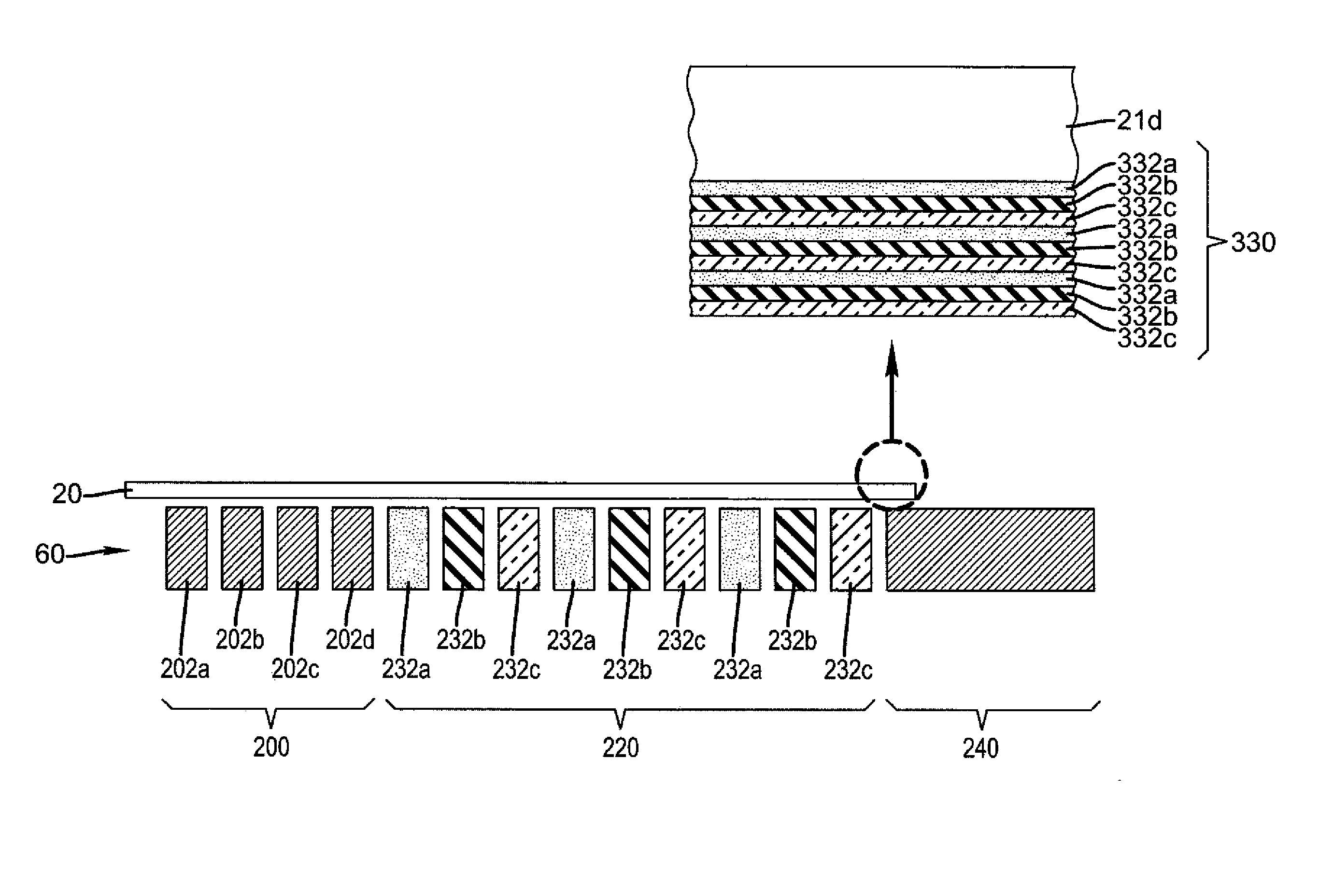
[0220]The purpose of this example was to prepare a TFT device with dielectric, semiconductor, and protection layers prepared by the ALD coating apparatus described above. This thin film transistor device (TFT) is comprised of a glass substrate, an ITO (indium tin oxide) gate electrode, a 1100 Å thick Al2O3 dielectric layer, a 200 Å thick ZnO layer, evaporated Al metal source / drain electrodes, and a 200 Å Al2O3 protection layer. The device used to prepare the Al2O3 and ZnO layers has been described in detail in FIGS. 5 to 12 herein. A 2.5×2.5 inch square (62.5 mm square) piece of ITO coated glass was positioned on the platen of this device, held in place by a vacuum assist and heated to 200° C. The platen with the glass substrate was positioned under the coating head that directs the flow of the active precursor gasses. The spacing between the ITO substrate and the coating head was adjusted using a micrometer to 30 microns.

[0221]The coating head has isolated channels through which fl...

example 2

[0222]The purpose of this example was to prepare a TFT device that had a transparent, conductive gate electrode of In-doped ZnO prepared by the same ALD coating system used for the dielectric and semiconductor layers. The devices had the following cross sectional composition: glass substrate / In-doped ZnO gate electrode / Al2O3 dielectric / ZnO semiconductor / Al source and drain electrodes. The In-doped ZnO gate electrode, layer 7A, was prepared as for the ZnO semiconductor layer, except that a flow of trimethylindium vapor is added to the flow of diethyl zinc at a flow rate of 40 sccm, and the layer was grown to approximately 2000 Å thick. The resistivity of the In-doped ZnO gate electrode layer was measured to be 3.3E-02 ohm*cm. An Al2O3 dielectric layer (7B) and a ZnO semiconductor layer (7C) were then coated onto the top of layer 7A using the settings specified in Table 1. Aluminum source and drain contacts were evaporated onto the top of layer 7C through a shadow mask, yielding thin ...

example 3

[0223]The purpose of this example was to prepare a TFT device that had a transparent, conductive gate electrode of In-doped ZnO prepared by the same ALD coating system used for the dielectric, semiconductor, and protection layers. The devices had the following cross sectional composition: glass substrate / In-doped ZnO gate electrode / Al2O3 dielectric / ZnO semiconductor / Al source and drain electrodes / Al2O3 protection layer. The sample was prepared as for Example 2 and electrically tested, and subsequently the protective layer was applied using the ALD coating system and the conditions listed for the protection layer in Table 1 above. The sample was then electrically tested again. Electrical test results for the above device (sample 3) having the In-doped ZnO gate electrode are shown below in Table 2 and are compared to a those of sample 2, which was identical except that it had no protection layer.

TABLE 2Average MobilityAverageSample(cm2 / Vs)Ion / Io / ff1(Devices with ITO gate5.34 × 108elec...


PUM

PropertyMeasurementUnit
temperatureaaaaaaaaaa
speedaaaaaaaaaa
separation distanceaaaaaaaaaa

Abstract

The present invention relates to a process of making thin film electronic components and devices, such as thin film transistors, environmental barrier layers, capacitors, insulators and bus lines, where most or all of the layers are made by an atmospheric atomic layer deposition process.

Description

CROSS-REFERENCE TO RELATED APPLICATIONS[0001]The present application is related to U.S. application Ser. No. 11 / 392,007, filed Mar. 29, 2006 by Levy and entitled, “PROCESS FOR ATOMIC LAYER DEPOSITION,” U.S. application Ser. No. 11 / 392,006, filed Mar. 29, 2006 by Levy and entitled “APPARATUS FOR ATOMIC LAYER DEPOSITION,” U.S. application Ser. No. 11 / 620,738, filed Jan. 8, 2007 by Levy and entitled “DELIVERY DEVICE FOR DEPOSITION,” U.S. application Ser. No. 11 / 620,740, filed Jan. 8, 2007 by Nelson et al. and entitled “DELIVERY DEVICE COMPRISING GAS DIFFUSER FOR THIN FILM DEPOSITION,” U.S. application Ser. No. 11 / 620,744, filed Jan. 8, 2007 by Levy and entitled, “DEPOSITION SYSTEM AND METHOD USING A DELIVERY HEAD SEPARATED FROM A SUBSTRATE BY GAS PRESSURE,” U.S. application Ser. No. ______ (docket 93187), filed Jan. 26, 2007 by Peter Cowdery-Corvan et al. and entitled, “PROCESS FOR ATOMIC LAYER DEPOSITION,” U.S. application Ser. No. ______ (docket 94077), filed concurrently herewith by...

Claims


Application Information

Patent Timeline
Patent Type & Authority Applications(United States)
IPC IPC(8): H01L21/336
CPCC23C16/407C23C16/45551H01L27/1214C23C16/545C23C16/45595B33Y80/00H01L27/1259H01L27/1225
Inventor NELSON, SHELBY F.LEVY, DAVID H.IRVING, LYN M.COWDERY-CORVAN, PETER J.FREEMAN, DIANE C.ELLINGER, CAROLYN R.
Owner EASTMAN KODAK CO
Why Eureka
Try Eureka