

Composite stretch yarn, process and fabric
a technology of composite stretch yarn and stretch yarn, applied in the field of composite stretch yarn, can solve the problems of poor elasticity of elastic polyester fabrics, and achieve the effect of excellent stretch recovery and great elasticity
- Summary
- Abstract
- Description
- Claims
- Application Information
AI Technical Summary
Benefits of technology
Problems solved by technology
Method used
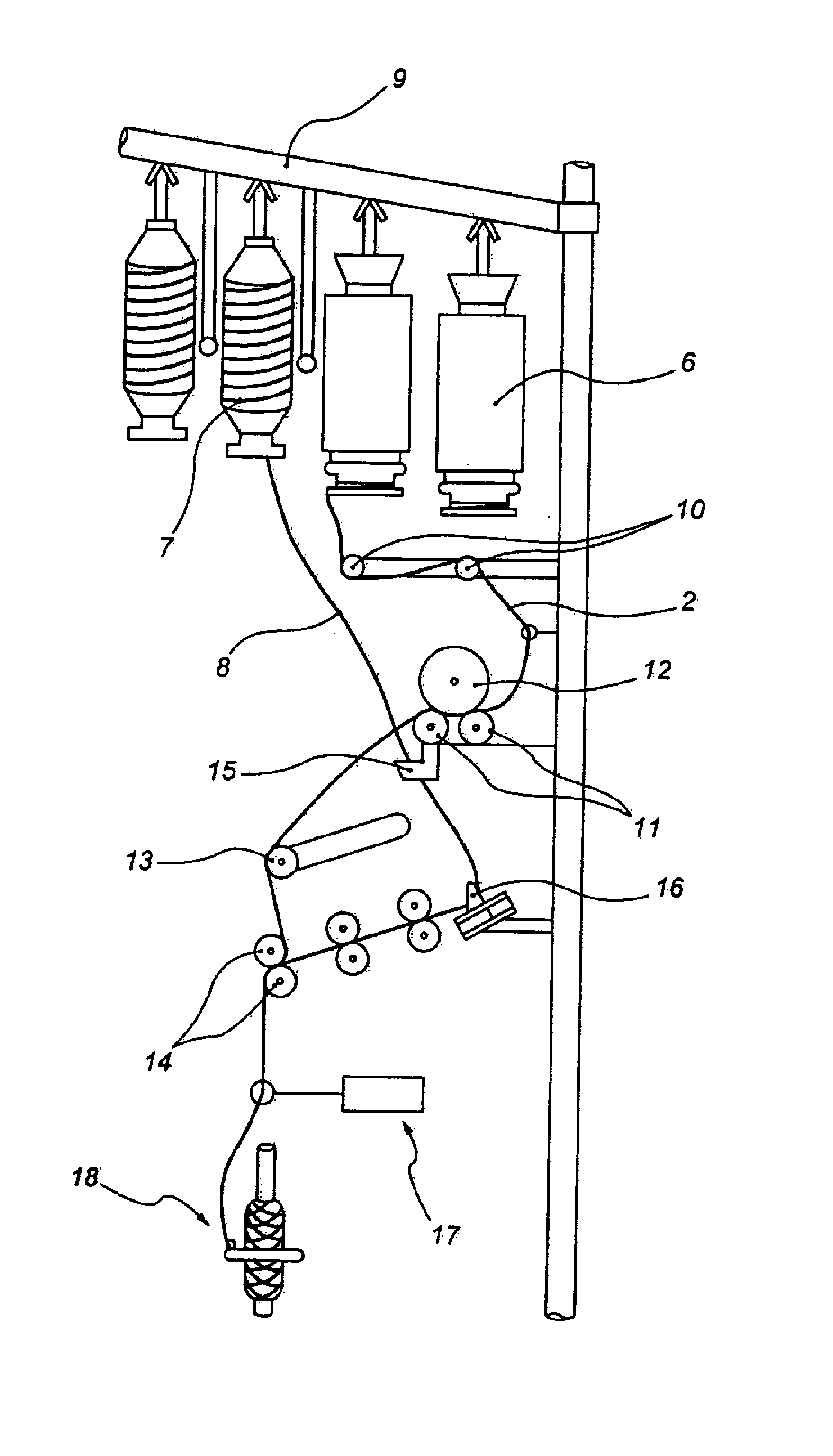
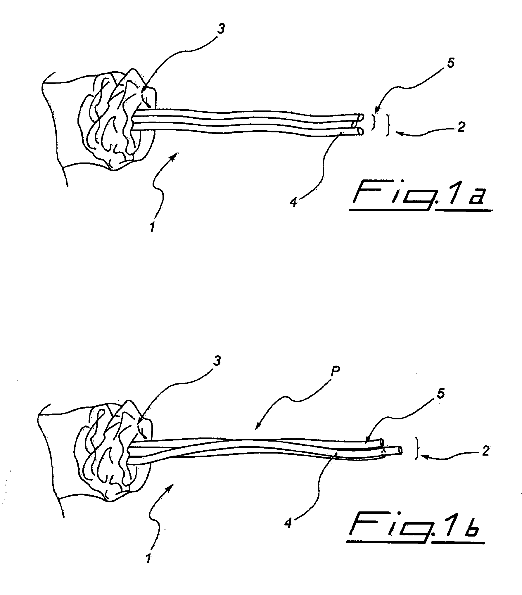
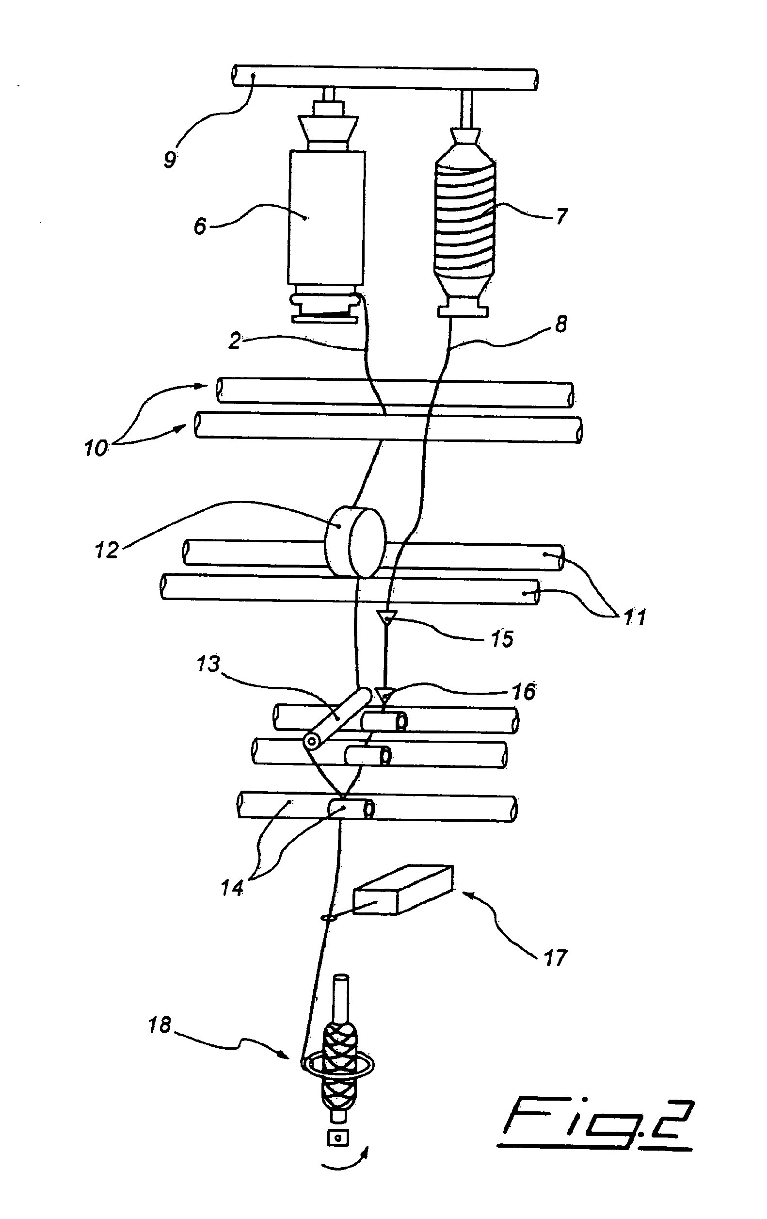
Image

Examples
example 1
Yarn Count Test
[0067]ZWEIGLE L 232 (Zweigle, Germany)
[0068]120 yards of yarn is wound to hank form using a Zweigle device. The hank was weighted using a Metier PM600 (Metier, Switzerland) weight scale. The yarn count was calculated using dtex count system chart. This test was repeated 5 times for consistency and accuracy.
example 2
Yarn Evenness Test
[0069]USTER TESTER−4 (Uster, Switzerland)
[0070]Yarn package was set on the creel of the Uster tester-4.
[0071]The following parameters were set:[0072]Yarn name was entered[0073]“Yarn” was selected as the setting for material class[0074]Yarn count was entered[0075]“Uster statistic section can not be accepted” has been selected[0076]“Cotton” was entered as the setting for Raw material[0077]The value of Fibre micronare was entered
[0078]UT 4-S section, Numbers of packages was set as “5”; number of tests was set as “1”; test speed was set as “400 m / min”; testing time was set as “0.5”; measurement slot was set as “automatic”; sucker was set as “60%”; test mode was set as “normal”; diagram resolution was set as “standard”
example 3
Strength, Elasticity and Breaking Force Measurement
[0079]USTER TENSORAPID−3 DEVICE (Uster, Switzerland).
[0080]Yarn was placed on the creel of the Uster tensorapid−3 device.
[0081]Yarn was passed through the spring guide.
[0082]The parameters entered in the program were:[0083]“Synthetic yarn” option was selected[0084]Measured yarn count (Example 1) was entered as Dtex yarn count system[0085]Number of the test was set to “50”[0086]Testing speed was adjusted to “2000 m / min”[0087]Clamp pressure was set to “30%”[0088]Suct-off pressure in the device was set to “50%”[0089]Blowing jets was set to “off” position[0090]Yarn change was set to “IX” position[0091]Yarn tensioner was set to “out” position[0092]Type of measure was set to “test automatic” position
PUM
| Property | Measurement | Unit |
|---|---|---|
| elongation | aaaaa | aaaaa |
| elongation | aaaaa | aaaaa |
| elongation at break | aaaaa | aaaaa |
Abstract
Description
Claims
Application Information