Method in UE supporting synchronization signals, method in base station supporting synchronization signals and devices

A technology for synchronizing signals and signals, applied in radio transmission systems, digital transmission systems, electrical components, etc., can solve problems such as narrow beams, achieve the effect of improving transmission efficiency and saving signaling overhead

Active Publication Date: 2018-04-24
SHANGHAI LANGBO COMM TECH CO LTD
View PDF9 Cites 10 Cited by
  • Summary
  • Abstract
  • Description
  • Claims
  • Application Information

AI Technical Summary

Problems solved by technology

The beams formed by multi-antenna beamforming are generally narrow, so the coverage of synchronization signals is a problem that needs to be solved

Method used


Image

  • Method in UE supporting synchronization signals, method in base station supporting synchronization signals and devices
  • Method in UE supporting synchronization signals, method in base station supporting synchronization signals and devices
  • Method in UE supporting synchronization signals, method in base station supporting synchronization signals and devices

Examples


Embodiment 1

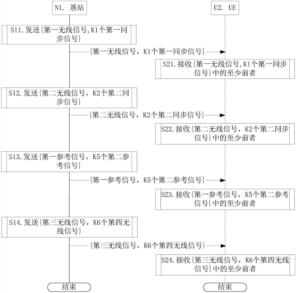
[0287] Embodiment 1 illustrates the flow chart of wireless transmission, as attached figure 1 shown. attached figure 1 In , the base station N1 is the serving cell maintenance base station of the UE U2.

[0288] For N1, send {first wireless signal, K1 first synchronization signals} in step S11; send {second wireless signal, K2 second synchronization signals} in step S12; send {first reference signal, K5 second reference signals}; send {third wireless signal, K6 fourth wireless signal} in step S14.

[0289] For U2, at least the former of {first wireless signal, K1 first synchronization signals} is received in step S21; at least the former of {second wireless signal, K2 second synchronization signals} is received in step S22; At least the former of {first reference signal, K5 second reference signals} is received in step S23; and at least the former of {third wireless signal, K6 fourth wireless signal} is received in step S24.

[0290] In Embodiment 1, the second time-freque...

Embodiment 2

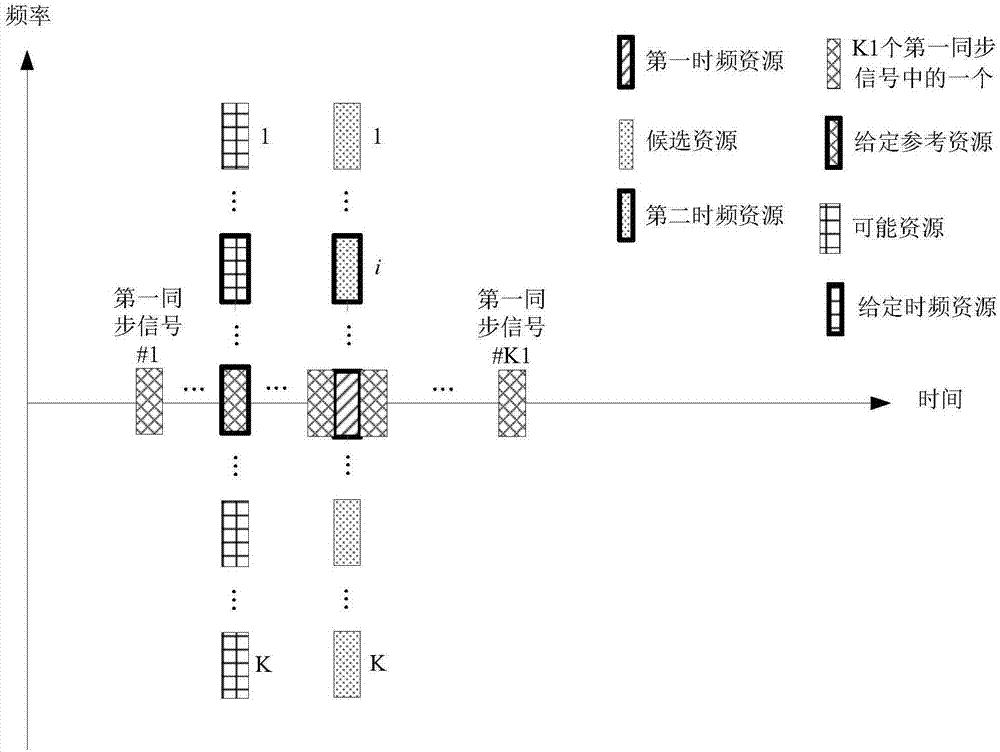
[0312] Embodiment 2 illustrates {first time-frequency resource, second time-frequency resource, K candidate resources, resource mapping of K1 first synchronization signals, given time-frequency resource, K possible resources, given reference resource} , and the schematic diagram of the association between the position of the second time-frequency resource in the K candidate resources and {the first time length, R1 antenna ports}, as shown in the attached figure 2 mentioned.

[0313]In Embodiment 2, the first synchronization signal in the first wireless signal and the K1 first synchronization signals form K3 first synchronization signals, and K3 is the sum of K1 and 1. The time domain resources occupied by the K3 first synchronization signals are orthogonal. The K candidate resources completely overlap in the time domain and are orthogonal in the frequency domain. The first time-frequency resource and the K candidate resources occupy the same time resource in the time domain...

Embodiment 3

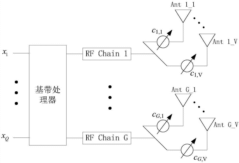
[0331] Embodiment 3 illustrates the schematic diagram of the antenna structure, as attached image 3 shown.

[0332] attached image 3 , the communication node is equipped with G antenna groups, and the G antenna groups correspond to G RF (Radio Frequency, radio frequency) chains (chains) respectively. One antenna group includes V antennas, G is a positive integer, and V is a positive integer. For 1≤g≤G, the antennas in antenna group #g include the attached image 3 In {Ant g_1, Ant g_2, ..., Ant g_V}, the antennas in the antenna group #g pass the analog beamforming vector c g Perform analog beamforming, where c g is a V×1-dimensional vector, and the analog beamforming vector corresponding to one antenna group is composed of the weighting coefficients on the V antennas included in the antenna group, that is, c g =[c g,1 ... c g,v ].


PUM


Abstract

The invention discloses a method in UE supporting synchronization signals, a method in a base station supporting the synchronization signals and devices. The UE receives a first wireless signal on a first time frequency resource and receives a second wireless signal on a second time frequency resource. The second time frequency resource is one in K candidate resources. A position of the second time frequency resource in the K candidate resources is used for determining at least one of {first time duration and R1 antenna ports}. The K is a positive integer greater than 1. The at least one of {length of CP corresponding to the first wireless signal, the length of the CP corresponding to the second wireless signal} is equal to the first time length. The R1 is the positive integer.

Description

technical field [0001] The present invention relates to a method and device for downlink transmission in a wireless communication system supporting synchronization signals, in particular to a solution and device for downlink transmission in a wireless communication system using MIMO (Multiple Input Multiple Output) technology. Background technique [0002] Massive MIMO has become a research hotspot in the next generation of mobile communications. In large-scale MIMO, multiple antennas use beamforming to form narrower beams pointing in a specific direction to improve communication quality. The beams formed by multi-antenna beamforming are generally narrow, so the coverage of synchronization signals is a problem that needs to be solved. [0003] 3GPP (3rd Generation Partner Project, third generation partnership project) RAN (RadioAccess Network, wireless access network) WG (Working Group, working group) #74bis meeting proposed a beam sweeping (Beam Sweeping) scheme, namely T...

Claims


Application Information

Patent Timeline
Patent Type & Authority Applications(China)
IPC IPC(8): H04L27/26H04B7/0413
CPCH04B7/0413H04L27/2655
Inventor 张晓博
Owner SHANGHAI LANGBO COMM TECH CO LTD
Why Eureka
Try Eureka