Supercharge Your Innovation With Domain-Expert AI Agents!

Cooling unit for synthetic yarn

A cooling device, wire technology, used in textiles and papermaking, etc., can solve problems such as cooling liquid infiltration

Active Publication Date: 2021-11-19
OERLIKON TEXTILE GMBH & CO KG
View PDF10 Cites 0 Cited by
  • Summary
  • Abstract
  • Description
  • Claims
  • Application Information

AI Technical Summary

Problems solved by technology

However, due to the twisted yarn structure, penetration of cooling liquid into the twisted yarn is a problem

Method used


Image

  • Cooling unit for synthetic yarn
  • Cooling unit for synthetic yarn
  • Cooling unit for synthetic yarn

Examples


Embodiment Construction

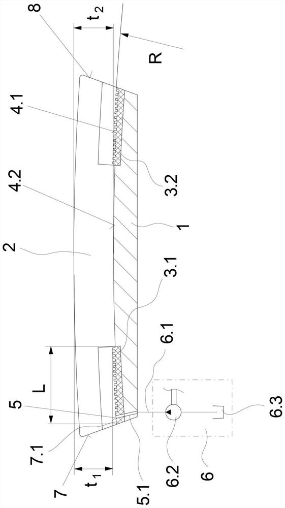
[0023] exist figure 1 , Figure 2.1 and Figure 2.2 , a first exemplary embodiment of a cooling device according to the invention is illustrated in several views. figure 1 Schematically shows a longitudinal sectional view of the cooling device according to the invention, in Figure 2.1 and Figure 2.2 A cross-sectional view of a cooling device according to the invention is shown in each case. In the absence of explicit reference to any one of the figures, the following description applies to said figures.

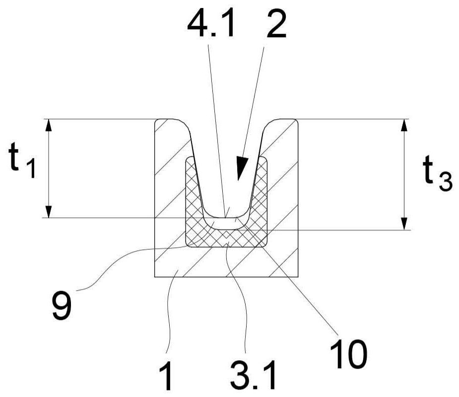
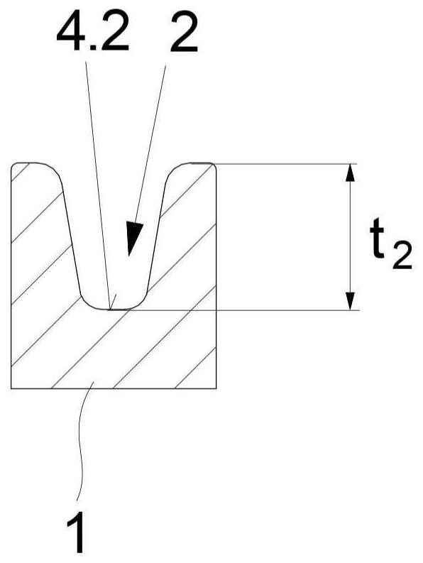
[0024] A first exemplary embodiment of a cooling device according to the invention comprises an elongated radiator 1 . An open cooling groove 2 extends on the upper side of the heat sink 1 . The cooling groove 2 extends between a wire inlet 7 and a wire outlet 8 formed at the end face of the heat sink 1 . At the wire entry 7 , the ceramic insert 3 . 1 is held in the cooling groove 2 on the heat sink 1 . The ceramic insert 3.1 is integrated in the cooling groove 2 an...


PUM

PropertyMeasurementUnit
radiusaaaaaaaaaa

Abstract

The invention relates to a cooling device for synthetic threads, especially twisted threads in the deformation zone, said cooling device comprising an elongated heat sink with an open for guiding said thread Cooling grooves. The cooling groove is connected via a metering opening to a metering device for supplying cooling liquid. Due to the dynamic properties of the wires, in order to obtain uniform wetting and intensive cooling, the heat sink comprises at the wire inlet at least one ceramic insert forming corrugated grooves inside the cooling grooves bottom, and the wire can be guided in contact on the surface of the ceramic insert to which the metering opening is assigned. Thus, cooling liquid can be continuously supplied to the wire over longer distances.

Description

technical field [0001] The invention relates to a cooling device for synthetic threads, especially twisted threads in the deformation zone, said cooling device comprising an elongated heat sink with an open for guiding said thread A cooling groove connected via a metering opening in the bottom of the groove to a metering device for supplying cooling liquid. Background technique [0002] During the production of synthetic threads, it is known to crimp the multifilaments produced in the melt spinning process in a downstream process for textile purposes. In this way, the synthetic thread is given a structure similar to natural fibers. The further processing of the synthetic thread takes place by means of a texturing machine which has a plurality of processing stations in order to crimp a corresponding thread at each processing station. The crimping of the thread is also known as so-called "texturing" and can be achieved by so-called false twisting. Here, mechanical false twi...

Claims


Application Information

Patent Timeline
Patent Type & Authority Patents(China)
IPC IPC(8): D02J13/00
CPCD02J13/00D02J13/003D02J13/008
Inventor S·康拉德P·容贝克T·穆恩斯特曼T·拉马克斯
Owner OERLIKON TEXTILE GMBH & CO KG
Features
  • R&D
  • Intellectual Property
  • Life Sciences
  • Materials
  • Tech Scout
  • Unparalleled Data Quality
  • Higher Quality Content
  • 60% Fewer Hallucinations
Learn More