
Charging base for cordless irons

A base, wireless technology, applied in the direction of hand irons, ironing boards, applications, etc., can solve the problems of not allowing the ergonomic use of irons, fatigue, etc.

Active Publication Date: 2015-11-25
SEB SA
View PDF5 Cites 0 Cited by
  • Summary
  • Abstract
  • Description
  • Claims
  • Application Information

AI Technical Summary

Problems solved by technology

[0003] However, such a charging base has the disadvantage that it restricts the user from moving the iron in a linear motion on the longitudinal axis of the ramp when the user desires to place the iron on the base
This limitation does not allow the ergonomic use of the iron and multiple ironings can be tiring

Method used


Image

  • Charging base for cordless irons
  • Charging base for cordless irons
  • Charging base for cordless irons

Examples


Embodiment Construction

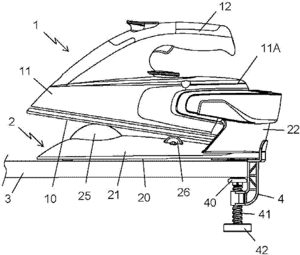
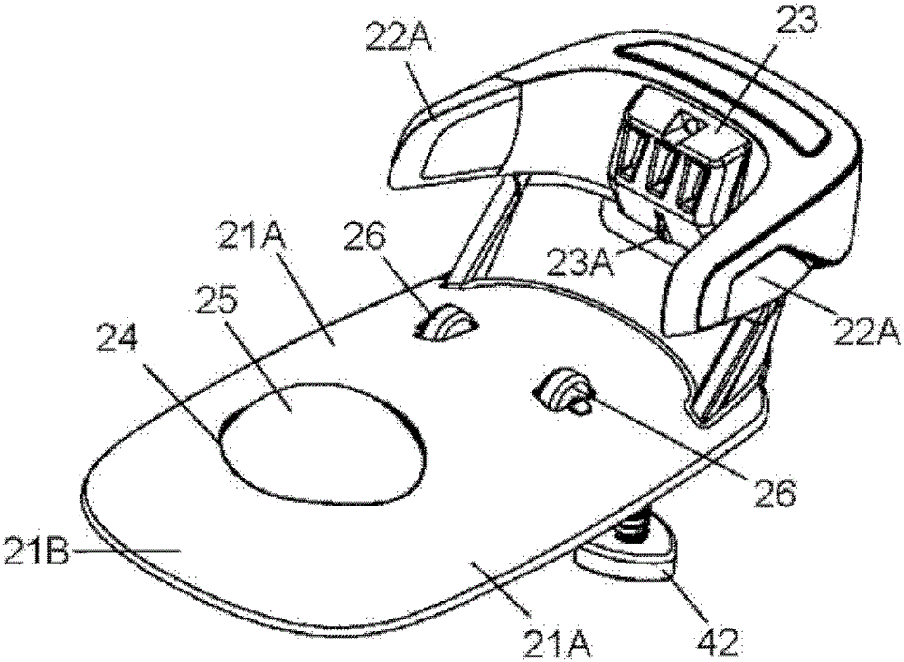
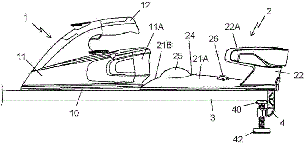
[0033] Only elements necessary for understanding the invention are shown. In order to facilitate reading of the drawings, the same elements are provided with the same reference numerals in each figure.

[0034] figure 1 An ironing appliance is shown comprising a cordless steam iron 1 arranged on a charging base 2 . The iron 1 generally comprises a flat sole 10 equipped with holes for the discharge of steam and on which is mounted a plastic housing 11 containing a water reservoir and having a handle 12 for holding the iron .

[0035] The soleplate 10 of the iron is in thermal contact with a heating body, not shown, consisting of an aluminum cast part, which is connected to the soleplate 10, which is integrated in the housing 11 and which has, in a manner known per se, a steam generator. Evaporation chamber and electrical resistance of at least 1400W and preferably about 2000W.

[0036] In order for the cordless iron 1 to have an autonomy of more than 1 minute during multipl...


PUM


Abstract

The station has a lower surface resting on a support surface i.e. iron table, and a soleplate of an iron rested on a base during inactive ironing phases for allowing exchange of energy between the station and the iron. The base is bordered on sides by access ramps (21A, 21B) descending in direction of lower surface and allowing transfer of the iron from the surface to the soleplate by sliding along the access ramps. The access ramps provide inclination in the order of 25 degrees with respect to the lower surface. An independent claim is also included for an ironing appliance comprising a cordless iron.

Description

technical field [0001] The present invention relates to a charging base for a cordless iron equipped with an ironing soleplate, and more particularly to a base having a lower surface for resting against a surface such as an ironing table and the base has a base on which the soleplate of the iron is placed when no ironing work is in progress to allow energy exchange between the charging base and the iron. Background technique [0002] Patent US3745676 discloses an ironing device, which includes a wireless iron and a charging base, the charging base has a base, the wireless iron should be set on the base, to allow the energy exchange between the charging base and the wireless iron The base plate is heated and the charging base is connected to the grid. The charging base has guide ramps allowing the iron to be brought onto the base by sliding the iron in the longitudinal direction of the base in order to insert the plug carried by the rear of the iron into the electrical conne...

Claims


Application Information

Patent Timeline
Patent Type & Authority Patents(China)
IPC IPC(8): D06F79/02D06F75/38D06F75/24
CPCD06F79/026D06F75/14D06F81/003
Inventor 让·伊夫·科班皮埃尔·文森特多米尼克·格吕斯塞兰·多梅克
Owner SEB SA
Learn More