Rolling element accommodating belt for linear guide apparatus and linear guide apparatus
A technology of rolling elements and guiding devices, applied in the direction of linear motion bearings, shafts and bearings, metal processing machinery parts, etc., can solve the problems of reducing the usability of installation operations
- Summary
- Abstract
- Description
- Claims
- Application Information
AI Technical Summary
Problems solved by technology
Method used
Image
Examples
no. 1 example
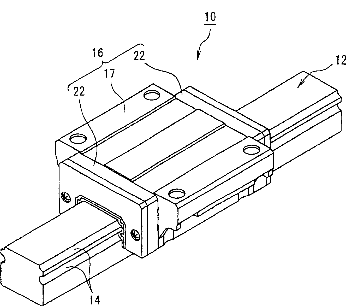
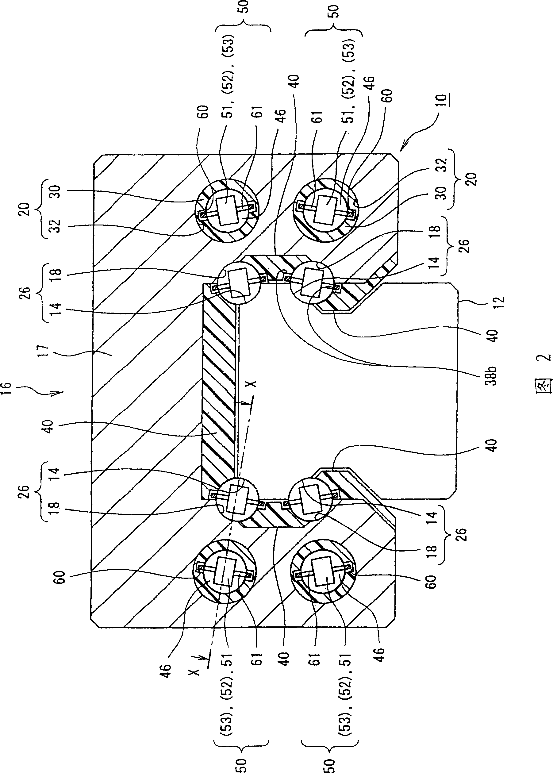
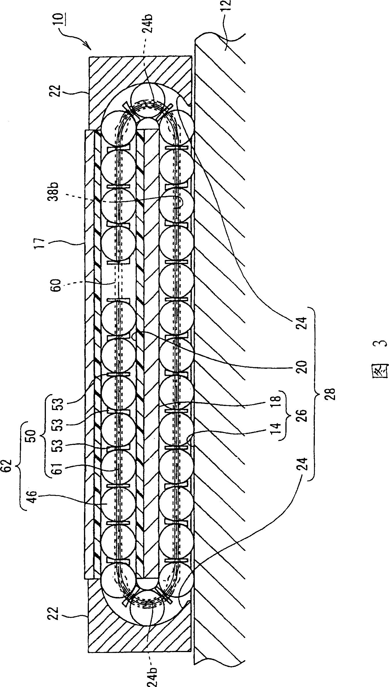
[0293] figure 1 is a perspective view of a linear guide according to a first embodiment of the linear guide provided with the rolling element accommodation belt used therein according to the invention. Figure 2 is a view for illustration figure 1 Cross-section of the carriage of the central linear guide. Fig. 3 is a sectional view along line X-X in the linear guide of Fig. 2 .
[0294] Such as figure 1 As shown in FIG. 2 , the linear guide 10 includes a guide rail 12 having a rolling element guide surface 14 and a slider 16 straddling the guide rail 12 so that the slider can move relative to the guide rail 12 .
[0295] The guide rail 12 has a square cross-sectional shape having four strip-shaped rolling element guide surfaces 14 each for one of two sides formed linearly in the longitudinal direction.
[0296] Such as figure 1 The shown slider 16 includes a slider body 17 and end caps 22 mounted on both ends of the slider body 17 in the axial direction. The axially c...
no. 2 example
[0346] Next, a linear guide according to a second embodiment of the present invention will be described. In this embodiment, the configuration is the same as that of the first embodiment except that a part of the structure of the rolling element accommodating belt is different. Therefore, only the difference on the rolling element accommodating belt will be described, and other parts will not be described.
[0347] As shown in FIG. 12 , the rolling element accommodation belt 72 has two kinds of spacers, namely, spacers 54 and spacers 55 . These spacers are alternately arranged in the alignment direction of the balls so that two types of rolling element accommodation portions, rolling element accommodation portions A and rolling element accommodation portions B, are alternately formed in the alignment direction of the balls 46 . The rolling element accommodating belt 50 according to this embodiment is different from that of the first embodiment in that these spacers 54, 55 eac...
no. 3 example
[0354] Next, a linear guide according to a third embodiment of the present invention will be described. In this embodiment, the configuration is the same as that of the above-mentioned embodiment except for the partial structure of the rolling element accommodating belt. Therefore, only the difference on the rolling element accommodating belt will be described, and other parts will not be described.
[0355] As shown in FIG. 13 , the rolling element accommodating belt 73 is different from the rolling element accommodating belt 50 according to the first embodiment in that it has two kinds of spacers, that is, a spacer 56 and a spacer 57; The directions are alternately arranged, that is, the rolling element accommodating portions A and the rolling element accommodating portions B are alternately formed in the direction in which the balls 46 are arranged.
[0356] The spacers 56 , 57 each have a nearly rectangular shape when viewed from their alignment direction, but their front...
PUM
 Abstract
Description
Claims
Application Information
 - R&D
- Intellectual Property
- Life Sciences
- Materials
- Tech Scout
- Unparalleled Data Quality
- Higher Quality Content
- 60% Fewer Hallucinations
Browse by: Latest US Patents, China's latest patents, Technical Efficacy Thesaurus, Application Domain, Technology Topic, Popular Technical Reports.
© 2025 PatSnap. All rights reserved.Legal|Privacy policy|Modern Slavery Act Transparency Statement|Sitemap|About US| Contact US: help@patsnap.com


