Voltage limiting ending type silicon controlled floating charger

A floating charger and voltage limiting technology, applied in the electronic field, can solve the problems of not being scientific enough, not realizing charging, etc.

Inactive Publication Date: 2018-05-25
CHONGQING NINGLAI SCI & TRADE
View PDF0 Cites 0 Cited by
  • Summary
  • Abstract
  • Description
  • Claims
  • Application Information

AI Technical Summary

Problems solved by technology

[0004] The reason why the most scientific charging has not been realized is that the current products either only use DC to charge the battery, but do not use a better method, such as constant current chargi

Method used


Image

  • Voltage limiting ending type silicon controlled floating charger
  • Voltage limiting ending type silicon controlled floating charger
  • Voltage limiting ending type silicon controlled floating charger

Examples


Embodiment Construction

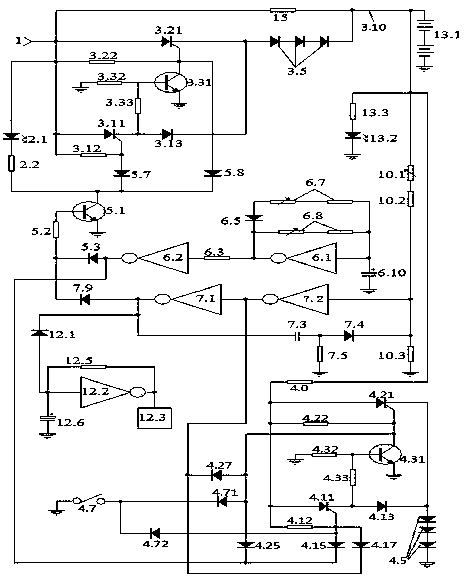
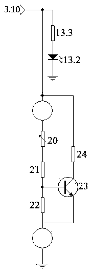
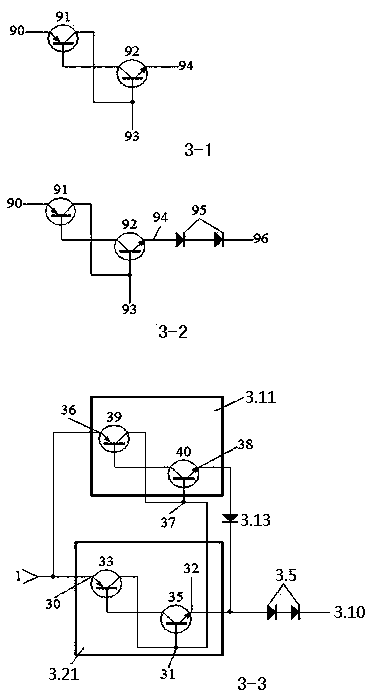
[0099] figure 1 An example of an implementation artifact is given, figure 2 It is the dummy load diagram used for detection. image 3 It is the schematic diagram of the one-way thyristor and the innovative thyristor.

[0100] 1. Selection of components: 1. The inverters are welded with Schmidt circuit.

[0101] 2. All thyristors are unidirectional thyristors.

[0102] 3. The feedback capacitor is a non-polar capacitor.

[0103] 4. The power of the discharge resistor is 1W.

[0104] 2. Make the circuit control board, welding components: connect figure 1 Make the circuit control board according to the schematic diagram, connect figure 1 Schematic of soldered components.

[0105] 3. Power-on inspection and debugging.

[0106] Check that the welding is correct, and you can conduct power-on inspection and debugging.

[0107] 1. Power-on inspection of the innovative thyristor, if the innovative thyristor is image 3 Shown in 3-2.

[0108] An inspection of innovative SCRs...


PUM

PropertyMeasurementUnit
Poweraaaaaaaaaa

Abstract

The invention discloses a voltage limiting ending type silicon controlled floating charger, and belongs to the field of electronic technique. The voltage limiting ending type silicon controlled floating charger consists of a trickle resistor, a creative silicon controlled charging unit, a creative silicon controlled discharging unit, an interface unit, a pulse unit, a voltage limiting ending unit,a load unit, a voice control unit and a process indicating unit; a charging and discharging coexisting pulse charging mode that the charging time is longer than the discharging time is formed by thecreative silicon controlled charging unit and the creative silicon controlled discharging unit together with the pulse unit and the interface unit; in the charging and discharging coexisting pulse charging mode, in one period of pulse, the creative silicon controlled discharging unit is turned off when the creative silicon controlled charging unit is turned on, the creative silicon controlled discharging unit is turned on when the creative silicon controlled charging unit is turned off, after a battery is full of electricity, the voltage limiting ending unit is turned on, the creative siliconcontrolled charging unit and the creative silicon controlled discharging unit are both turned off, voice reminding is emitted by the voice control unit, and trickle is provided for the charged batteryby the trickle resistor.

Description

technical field [0001] It belongs to the field of electronic technology. Background technique [0002] Our company applied for a series of security products some time ago, and this product must have a backup battery, otherwise, when there is no mains power, the security function will become a fake, and when there is no mains power, it may be the peak of security accidents when. So a backup battery is required. And the performance of the backup battery is directly related to the overall performance. [0003] But the backup battery must be charged and maintained, and the scientific maintenance of the backup battery is directly related to the life and capacity of the backup battery. Some sources believe that batteries are often not worn out, but damaged due to improper charging. Batteries in security equipment are special-purpose batteries, which have special requirements for volume and capacity, and are more demanding than general products. [0004] The reason why the mos...

Claims


Application Information

Patent Timeline
IPC IPC(8): H02J7/00
CPCH02J7/007H02J7/0003H02J7/0047H02J7/0063
Inventor 不公告发明人
Owner CHONGQING NINGLAI SCI & TRADE
Why Eureka
Try Eureka