An Optical Phased Array for Grating Lobe Compression

An optical phased array, phased array technology, applied in the field of optical phased array, can solve the problem of large grating lobes, and achieve the effect of overcoming high strength

Active Publication Date: 2019-12-27
TSINGHUA UNIV
View PDF4 Cites 0 Cited by
  • Summary
  • Abstract
  • Description
  • Claims
  • Application Information

AI Technical Summary

Problems solved by technology

[0004] Although the current optical phased array scanning technology has achieved high resolution, high precision, and fast scanning, the traditional optical phased array still has the following technical bottlenecks that restrict its popularization: In terms of grating lobe strength, the traditional optical phased array large grating lobe

Method used


Image

  • An Optical Phased Array for Grating Lobe Compression
  • An Optical Phased Array for Grating Lobe Compression
  • An Optical Phased Array for Grating Lobe Compression

Examples


Embodiment Construction

[0021] In order to make the object, technical solution, and advantages of the present invention clearer, the present invention will be further described in detail below with reference to the accompanying drawings and examples.

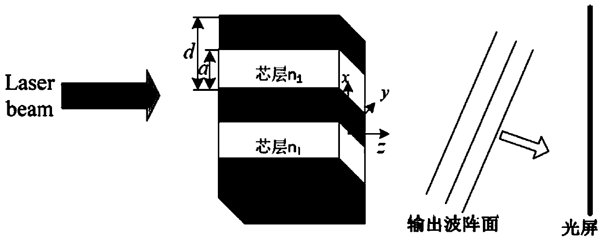
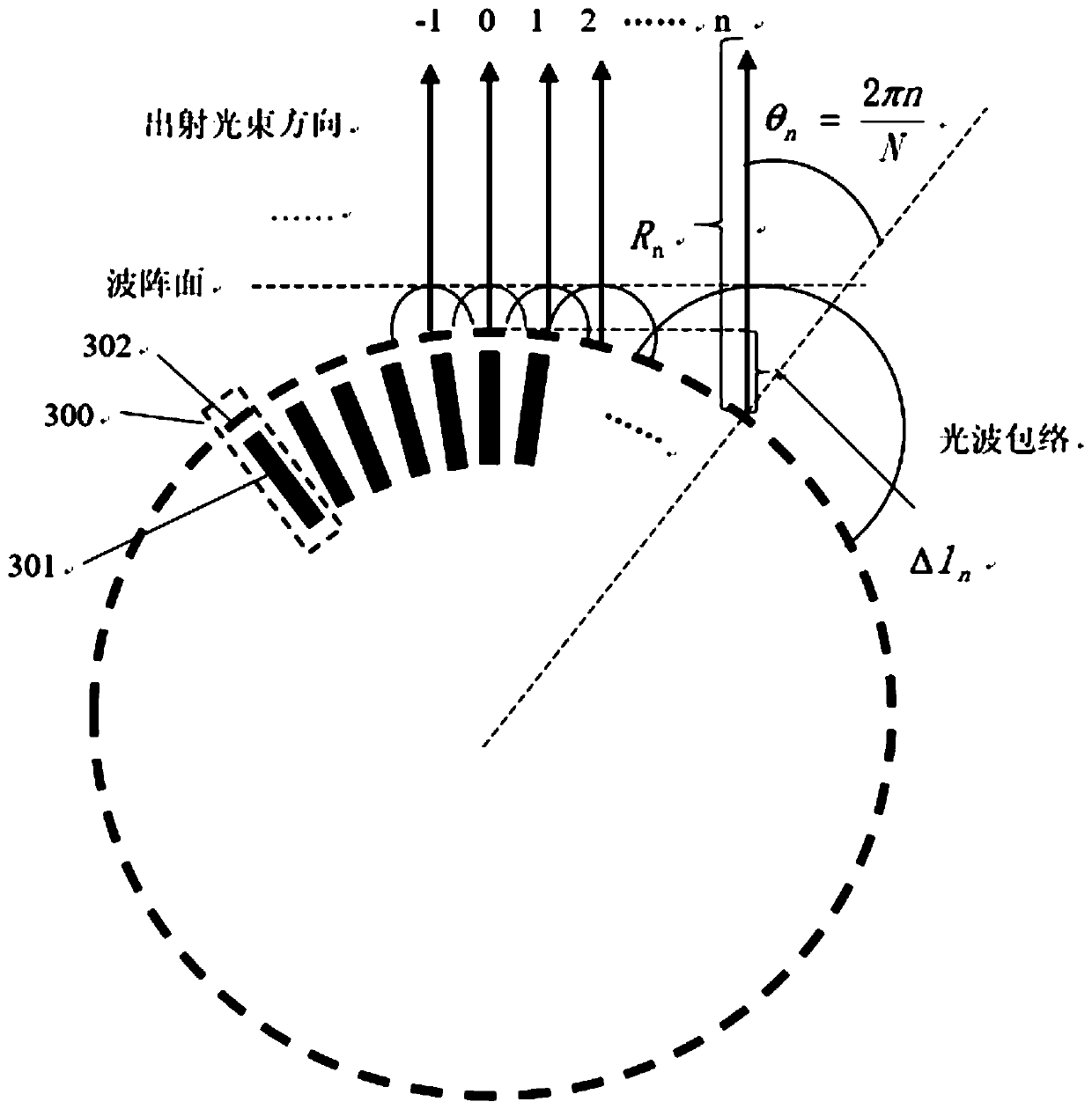
[0022] Figure 3a It is a schematic diagram of the structure of the annular optical phased array without amplitude weighting in the present invention. The annular phased array is made up of N phased array units, each phased array unit includes a phase modulator 301 for adjusting the additional phase of the phased array unit 300, and the N phase modulators are arranged on a plane Arranged in a circular shape, the waveguide transmitting unit 302 at one end of each phase modulator faces outside the center of the circular ring, and N is a natural number. Depend on Figure 3a It can be seen that the circular optical phased array without amplitude weighting does not include injection-locked lasers.

[0023] Figure 3b It is a schematic diagram of the str...


PUM

PropertyMeasurementUnit
strengthaaaaaaaaaa

Abstract

The invention discloses an optical phased array used for grating lobe compression. The optical phased array is composed of N phased array units. The N phased array units are distributed in a circularring-shaped manner on a plane with N being a natural number. Each phased array unit comprises one phase modulator used for regulating additive phase of the phased array unit and one injection lockinglaser used for adjusting the field intensity amplitude. A first end of each phase modulator, facing the outside of the center of a circular ring shape, is equipped with a wave guide transmission unit.A second end of each phase modulator, facing the inside of the center of a circular ring shape, is in waveguide connection with each injection locking laser. The optical phased array used for gratinglobe compression helps achieve compression of grating lobe intensity.

Description

technical field [0001] The invention relates to the technical field of optical phased arrays, in particular to an optical phased array for grating lobe compression. Background technique [0002] Optical phased array technology (OPA—Optical Phased Array), which has become a research hotspot in recent years and has developed rapidly, is a new electronically controlled beam scanning technology, and its working principle is similar to that of microwave phased array. Its core components are composed of several phase modulation units. By controlling the applied voltage of the phase modulator, the additional refractive index inside the modulator can be controlled, so that the additional phase of the light field at the output end of each phase modulator can be controlled, so that the deflection of the propagation direction of the radiation beam can be realized. Optical phased array technology is a high-resolution, high-precision, and fast beam control technology with broad applicat...

Claims


Application Information

Patent Timeline
Patent Type & Authority Patents(China)
IPC IPC(8): G02F1/29
CPCG02F1/292
Inventor 熊兵刘学成罗毅孙长征郝智彪
Owner TSINGHUA UNIV
Why Eureka
Try Eureka