Die-cutting machine and die-cutting method thereof

A die-cutting machine and die-cutting technology, applied in metal processing, etc., can solve problems such as difficult disassembly, achieve high degree of automation, beautiful form, and improve die-cutting efficiency

Active Publication Date: 2018-07-06
马鞍山邦德医疗器械有限公司
View PDF7 Cites 7 Cited by
  • Summary
  • Abstract
  • Description
  • Claims
  • Application Information

AI Technical Summary

Problems solved by technology

[0005] Aiming at the problem that there is no dividing dotted line in product packaging in the prior art, and it is particularly difficult to disassemble, the present invention provides a die-cutting machine

Method used


Image

  • Die-cutting machine and die-cutting method thereof
  • Die-cutting machine and die-cutting method thereof

Examples


Embodiment 1

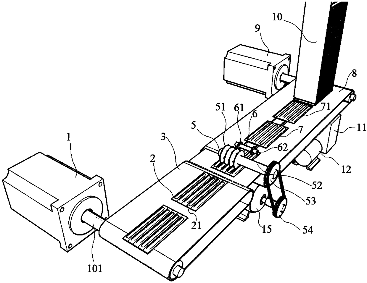
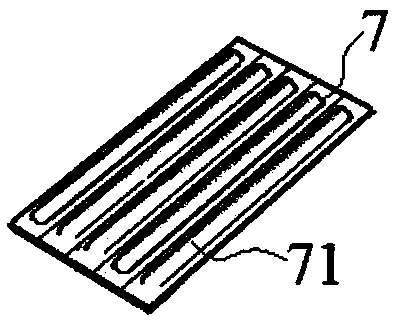
[0042] like figure 1 and figure 2 shown, with figure 1 A die-cutting machine includes a die-cutting template 4 and a die-cutting knife 5, the die-cutting template 4 is evenly distributed with several grooves, and the die-cutting knife 5 includes a die-cutting knife shaft 52 die-cutting blades 51 equal in number to the grooves, wherein the die-cutting blades 51 are located in the grooves. The die-cutting knife 5 rotates in the groove, and when the product group 7 before die-cutting arrives on the die-cutting template 4, the die-cutting knife 5 rotates to drive the product group 7 before die-cutting to move on the die-cutting template 4, and the die-cutting knife 5 and the groove, between the adjacent products 71 on the product group 7 before die-cutting, the die-cutting blade 51 cuts a dividing dotted line 21 to form the product group 2 after die-cutting. The distance between adjacent products 71 is equal to the distance between adjacent grooves and the distance between adj...

Embodiment 2

[0044] like figure 1 and figure 2 As shown, a die-cutting machine, on the basis of Embodiment 1, also includes a feeding conveyor belt 8, and the feeding conveyor belt 8 is located on the entrance side of the die-cutting template 4 and is adjacent to the die-cutting template 4. One end of the feed conveyor belt 8 is connected with the output shaft of the feed conveyor belt motor 9, and the output shaft and the driven shaft of the feed conveyor belt motor 9 are all fixed on the side plate by bearings. The other end of the feeding conveyor belt 8 is adjacent to the die-cutting template 4 and is connected with a driven shaft. The output shaft of the feeding conveyor belt motor 9 rotates to drive the feeding conveyor belt 8 to drive forward. The product group 7 before die-cutting includes a plurality of products 71 arranged side by side, and the products 71 are strip-shaped, and the distances between adjacent products 71 are equal. On the product group 2 after die-cutting, ther...

Embodiment 3

[0046] like figure 1 As shown, a die-cutting machine, on the basis of Embodiment 1 or 2, also includes a guide device 6, and the guide device 6 includes a material receiving pressure wheel 61 and a material receiving pressure shaft 62, and the material receiving pressure shaft 62 Two ends of each are provided with a receiving pressure wheel 61, and the guide device 6 is located above the end adjacent to the feeding conveyor belt 8 and the die-cutting template 4. The distance between the guide device 6 and the die-cutting blade 51 is less than the length of the product group 7 before die-cutting, which is convenient to play an effective guiding role. If the distance is too long, the product group 7 before the die-cutting does not reach the die-cutting blade 51. , there is still a possibility that a section may be stuck, blocked or the position of the product group 7 before die-cutting may move, so that the product group 7 before die-cutting cannot reach the die-cutting template...


PUM


Abstract

The invention discloses a die-cutting machine and a die-cutting method thereof, and belongs to the technical field of product packaging. The die-cutting machine includes a die-cutting template and a die-cutting tool. A plurality of grooves are formed in the die-cutting template evenly. The die-cutting tool includes die-cutting blades. The die-cutting blades are located in the grooves. The die-cutting method of the die-cutting machine includes the following steps that a feeding conveying belt motor, a vacuum sucker motor, a receiving conveying belt motor and a die-cutting motor are started; product groups before die-cutting are conveyed to a guiding device, receiving pressing wheels on a receiving pressing shaft press on both sides of each product group before the die-cutting, and the receiving pressing shaft rotates to drive the receiving pressing wheels to rotate; and the receiving pressing wheels drive the product groups before the die-cutting to move forwards to the die-cutting template, the die-cutting motor rotates, an output shaft of the die-cutting motor drives a die-cutting motor belt pulley to rotate, a die-cutting tool wheel rotates, a die-cutting tool shaft rotates, thedie-cutting blades drive the product groups before the die-cutting to rotate in the grooves, and die-cutting is achieved. According to the die-cutting machine and the die-cutting method thereof, the fact that dividing dotted lines can be added to product packaging is achieved, and splitting is fast and convenient.

Description

technical field [0001] The invention relates to the technical field of product packaging, in particular to a die-cutting machine and a die-cutting method thereof. Background technique [0002] For a complete set of small daily necessities, medical supplies and other industrial products, they are used one by one. When they are used separately, because there is no dividing dotted line in the product packaging, it is particularly difficult to disassemble. If there is no scissors, it is very difficult It is easy to damage the product. Even if some manufacturers add dividing dotted lines in the product packaging, it requires a lot of labor, time and energy consumption, low efficiency and high cost. [0003] Chinese utility model patent, authorized announcement number: CN 205058180 U, authorized announcement date: March 2, 2016, discloses a reciprocating circular flattening die-cutting machine, which involves the field of die-cutting, half of which is empty for circular flattenin...

Claims


Application Information

Patent Timeline
Patent Type & Authority Applications(China)
IPC IPC(8): B26F1/44B26D3/08B26D7/02B26D7/06B26D7/32
CPCB26D3/08B26D7/02B26D7/06B26D7/0625B26D7/32B26F1/44
Inventor 王伟春
Owner 马鞍山邦德医疗器械有限公司
Why Eureka
Try Eureka