Top cover of power battery, assembly method thereof and power battery

A power battery and top cover technology, applied in battery cover/end cover, assembled battery machine, secondary battery manufacturing, etc., can solve the problem of low reliability, inability to guarantee the stability of poles and conductive blocks, poles and conductive blocks The problem of small contact area can achieve the effect of reducing the use of nuts and circlips, good axial positioning effect, and stable and reliable assembly structure

Pending Publication Date: 2018-08-03
JIANGSU ZENIO NEW ENERGY BATTERY TECH CO LTD
View PDF0 Cites 13 Cited by
  • Summary
  • Abstract
  • Description
  • Claims
  • Application Information

AI Technical Summary

Problems solved by technology

Among them, threaded assembly is to process threads on the pole, and then use nuts to fix the pole and the top cover sheet. Since this method requires threading of the pole and nuts, the processing is complicated, the cost is high, and the assembly efficiency is low. product is heavy
The circlip assembly is to process a ring-shaped slot on the pole. By installing the circlip on the slot of the pole, it presses the top cover and other parts so that they cannot move axially, so that the pole and the pole are connected. The assembly between the top cover pieces; although this method has high reliability and can reduce the product weight compared with threade

Method used


Image

  • Top cover of power battery, assembly method thereof and power battery
  • Top cover of power battery, assembly method thereof and power battery
  • Top cover of power battery, assembly method thereof and power battery

Examples


Embodiment approach 1

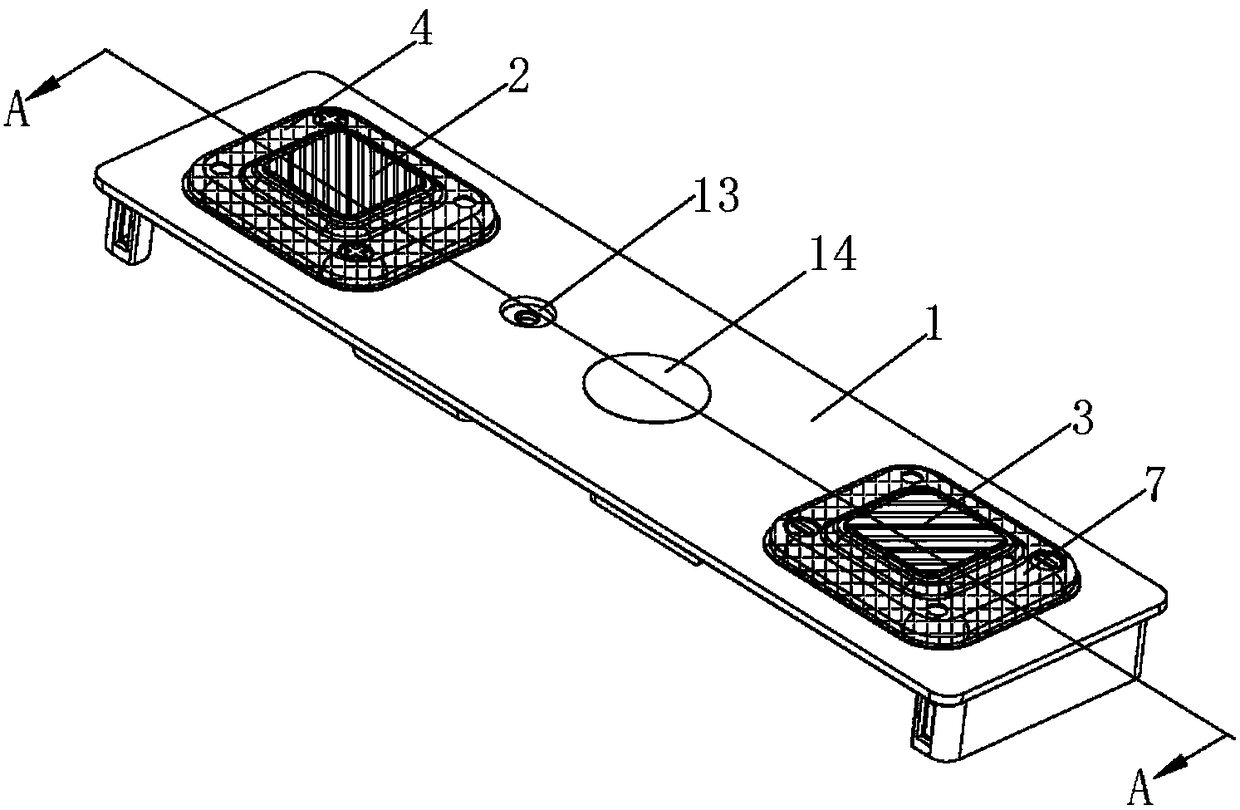
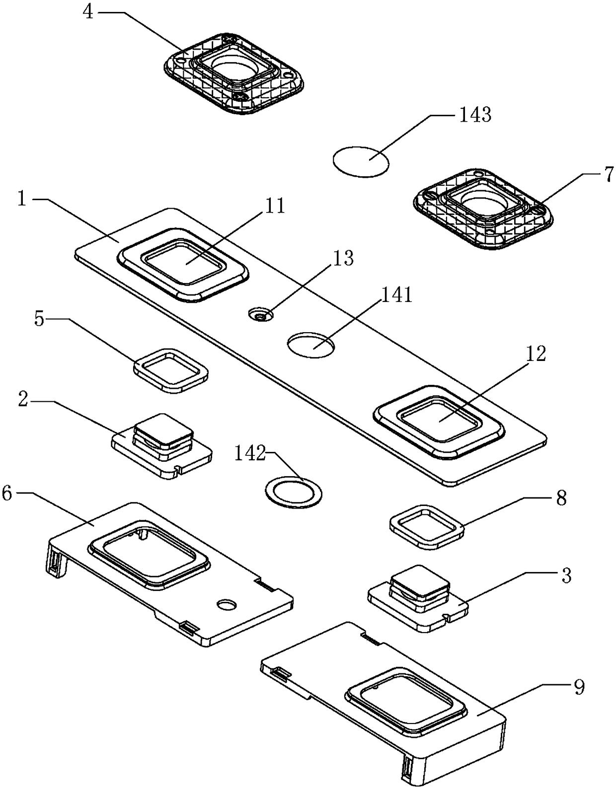
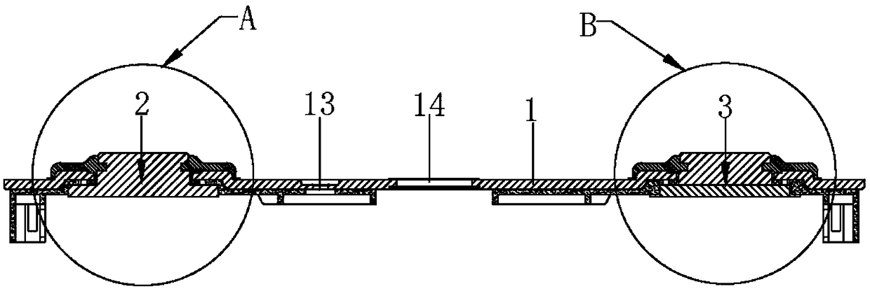
[0042] Such as Figure 1-11 As shown, a power battery top cover includes a top cover sheet 1 and a first pole 2, a second pole 3, a first installation hole 11, a second installation hole 12, and an explosion-proof valve 14 arranged on the top cover sheet 1. And the injection hole 13, the explosion-proof valve 14 includes the explosion-proof hole 141 arranged on the top cover sheet 1, the explosion-proof sheet 142 for sealing the explosion-proof hole 141, and the protective film 143 covering the explosion-proof hole 141; the first pole 2 is installed on the second In a mounting hole 11, the second pole 3 is installed in the second mounting hole 12, the first pole 2 includes a first base part 21 and a second base part 22, and the first base part 21 and the second base part 22 A first cylinder part 23 is arranged between them, and a first card groove is formed between the first base part 21, the first cylinder part 23 and the second base part 22; the first cylinder part 23 is sle...

Embodiment approach 2

[0052] Such as figure 2 As shown, a method for assembling the power battery top cover described in Embodiment 1 includes the following steps:

[0053] Step 1) Set the first sealing ring 5 on the fifth base part 24 of the first pole 2 to form the first pole 2 assembly, and set the second sealing ring 8 on the sixth base part of the second pole 3 34 forming the second pole 3 assembly;

[0054] Step 2) Install the first pole 2 assembly in the first installation hole 11 of the top cover sheet 1, and install the second pole 3 assembly in the second installation hole 12 of the top cover sheet 1;

[0055] Step 3) Install the first insulating member 6 between the second base portion 22, the first sealing ring 5 and the top cover sheet 1, install the third insulating member 9 on the fourth base portion 32, the second sealing ring 8 and between the top cover sheet 1;

[0056] Step 4) Using the overmolding injection molding process respectively, the conductive plastic part 4 is faste...

Embodiment approach 3

[0060] Such as Figure 12 As shown, a power battery includes a bare cell 20, an electrolyte, a battery casing 10 for containing the bare cell 20 and the electrolyte, and a top cover sealed and installed on the battery casing 10, and the positive electrode of the bare cell 20 The ear 30 is electrically connected to the first pole 2 on the top cover, and the negative pole ear 40 of the bare cell 20 is electrically connected to the second pole 3 on the top cover, which is the power battery provided in Embodiment 1 top cover. Compared with the existing power battery, the power battery of the present invention has fewer assembly parts and a compact and reliable structure, which can not only effectively ensure the working performance of the battery, but also effectively improve the production efficiency of the battery and reduce the production cost of the battery.


PUM

PropertyMeasurementUnit
Resistanceaaaaaaaaaa
Heat resistance temperatureaaaaaaaaaa

Abstract

The invention discloses a top cover of a power battery. The top cover of the power battery comprises a top cover sheet, a first terminal post, a second terminal post, a first mounting hole, a second mounting hole, an explosion-proof valve and a liquid filling hole, wherein the first terminal post, the second terminal post, the first mounting hole, the second mounting hole, the explosion-proof valve and the liquid filling hole are arranged on the top cover sheet; the first terminal post is mounted in the first mounting hole; the second terminal post is mounted in the second mounting hole; the first terminal post comprises a first matrix part and a second matrix part; a first column part is arranged between the first matrix part and the second matrix part; a first groove is formed among thefirst matrix part, the first column part and the second matrix part; a first seal ring sleeves the first column part; conductive plastic parts are arranged among the first matrix part, the first column part, the first seal ring and the top cover sheet; and a first insulating part is arranged among the second matrix part, the first seal ring and the top cover sheet. An H-shaped terminal post structure of the top cover of the power battery can achieve a good axial positioning effect on top cover parts, so the top cover of the power battery is compact and reliable in structure, dispenses with a riveting working procedure required by a T-shaped terminal post with a conductive block, reduces production cost and improves assembly efficiency.

Description

technical field [0001] The invention belongs to the technical field of power batteries, and in particular relates to a power battery top cover, an assembly method thereof, and a power battery. Background technique [0002] As an important part of the power battery, the top cover generally includes a top cover sheet, an explosion-proof valve, a liquid injection hole, a positive pole and a negative pole, etc. Among them, the pole is the internal and external conduction part of the power battery, one end of which is connected to the external circuit of the power battery, and the other end is connected to the battery cell inside the power battery to realize the charging and discharging function of the battery; when the battery is assembled, the positive pole needs to be Pass through the top cover and connect with the positive pole lug of the battery; the negative pole must pass through the top cover and connect with the negative pole of the battery; the assembly function require...

Claims


Application Information

Patent Timeline
IPC IPC(8): H01M2/04H01M2/08H01M2/26H01M10/04H01M50/147H01M50/184H01M50/188H01M50/528H01M50/531
CPCH01M10/0404H01M50/147H01M50/183H01M50/531Y02E60/10Y02P70/50
Inventor 王程李勇军姜斌何波林法稳
Owner JIANGSU ZENIO NEW ENERGY BATTERY TECH CO LTD
Why Eureka
Try Eureka