Linear conveyor system with minimum conveyor pitch

A technology for transmission systems and transmission components, applied in the direction of propulsion systems, conveyors, non-mechanical conveyors, etc.

Active Publication Date: 2020-09-22
KRONES AG
View PDF1 Cites 0 Cited by
  • Summary
  • Abstract
  • Description
  • Claims
  • Application Information

AI Technical Summary

Problems solved by technology

In addition, however, also the extension of the secondary part in the conveying direction, which usually has a carrier plate on which the magnets are mounted, can limit the reduction of the minimum achievable conveying distance

Method used


Image

  • Linear conveyor system with minimum conveyor pitch
  • Linear conveyor system with minimum conveyor pitch
  • Linear conveyor system with minimum conveyor pitch

Examples


Embodiment Construction

[0068] In the drawings described below, the same reference numerals designate the same elements. For greater clarity, identical elements will only be described the first time they appear. However, it is clear that variants and embodiments of elements described with reference to one of the figures can also be applied to corresponding elements in the remaining figures.

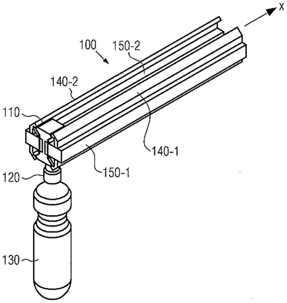
[0069] figure 1 A three-dimensional view of a linear conveyor system known from the prior art and described, for example, in DE 10 2013 218 389 A1 is shown. The illustrated linear conveyor system 100 includes a conveyor track having a first rail 140-1, a second rail 140-2, a first long stator 150-1, and a second long stator 150-2. The conveying system shown thus forms a double-rail system with linear motors on both sides.

[0070] Between the two rails, the transfer element 110 is systematically moved by means of magnetic interaction with the long stators 150-1 and 150-2. This conveying direction is indicate...


PUM


Abstract

The invention relates to a conveyor system for conveying containers (130) in a container processing facility, comprising a conveying track with at least one long stator (450) of a linear motor and a plurality of Conveying elements (410, 510, 610...), wherein the conveying elements are movably arranged on said conveying track and each have at least one secondary part (470, 1070, 1170) for magnetically interacting with at least one long stator ...), wherein at least one sequence of permanent magnets and / or electromagnets with alternating polarity is attached to the secondary part so that each conveying element can follow the conveying track via the magnetic interaction of the sequence of magnets with the long stator movement, and wherein the extension of at least the first and last magnet in each sequence is reduced and the arrangement of at least the first and last magnet on the secondary part is chosen such that the adjacent sequence ends of two consecutive conveying elements The magnets occupy a non-overlapping area perpendicular to the conveying direction.

Description

technical field [0001] The invention relates to a device for the controlled movement of individually controllable conveying elements for conveying containers, packs, labels, closures or other packaging means, in particular bottles or cans, in a facility for handling containers. Background technique [0002] Conveyor systems with linear motor drives, so-called linear conveyor systems, are well known in the prior art. The most prominent example is high-speed passenger trains based on maglev technology. However, conveyor systems with linear motor drives are also used in many industrial fields, especially for the individual conveying of individual items within production lines. [0003] For example, in DE 10 2013 218 389 A1 a linear conveyor system with a plurality of magnetic rotors for conveying bottles in a container processing plant is described. The rotor conveying the bottles thus moves while being driven by the magnetic interaction between the secondary part of the roto...

Claims


Application Information

Patent Timeline
Patent Type & Authority Patents(China)
IPC IPC(8): B65G54/02H02K41/03
CPCH02K41/031H02K7/08B65G54/02B60L13/10
Inventor 米夏亚多·诺伊鲍尔
Owner KRONES AG
Why Eureka
Try Eureka