Constant velocity joint integrated to wheel bearing and to axially adjustable hub

Inactive Publication Date: 2005-02-22
CSIK FRANK VICTOR
View PDF9 Cites 25 Cited by
  • Summary
  • Abstract
  • Description
  • Claims
  • Application Information

AI Technical Summary

Benefits of technology

It is an object of the present invention to provide a robust wheel support assembly for a wheeled vehicle wherein the CV joint's flexural center, that is to say its outer race proper, is placed more closely to the wheel center plane than is possible with current state of the art solutions, and by taking the opportunity

Problems solved by technology

It is known in the art that the typical method of packaging the hub in the front upright with the constant velocity “CV” joint in the case of independently suspended wheels presents a compromised steering geometry in front-wheel-drive “FWD” and all-wheel-drive vehicles, which is especially pronounced in the case of light trucks and Sport Utility Vehicles.
Within the scope of independent type suspension layouts, accepted wheel hub packaging practice does not make it feasible to achieve negative scrub radius with low kingpin angle, especially not on SUVs and light trucks, as any currently practiced approach to wheel bearing packaging solutions force the wheel end—or outboard—CV joint undesirably far inboard of the wheel rim's center plane.
Another undesirable byproduct of current state of the art CV joint packaging practice is that said CV joint's said outer race proper is cantilevered by virtue of

Method used


Image

  • Constant velocity joint integrated to wheel bearing and to axially adjustable hub
  • Constant velocity joint integrated to wheel bearing and to axially adjustable hub
  • Constant velocity joint integrated to wheel bearing and to axially adjustable hub

Examples


Embodiment Construction

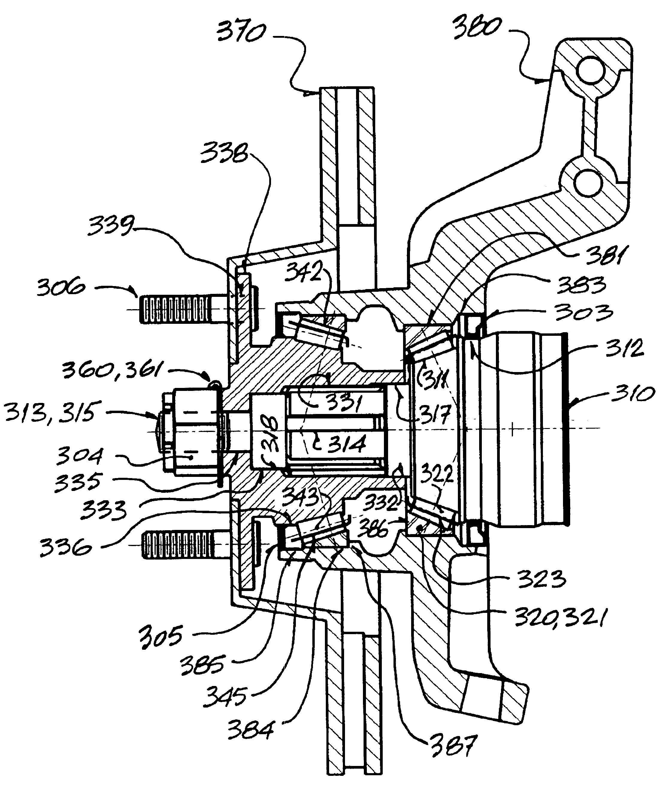
Referring to the drawings in greater detail and by reference characters thereto, in FIG. 1 there is illustrated a side elevation with broken out sectional view of the CV joint's outer race, noting the terminology referring to elements thereof and occurring throughout this document.

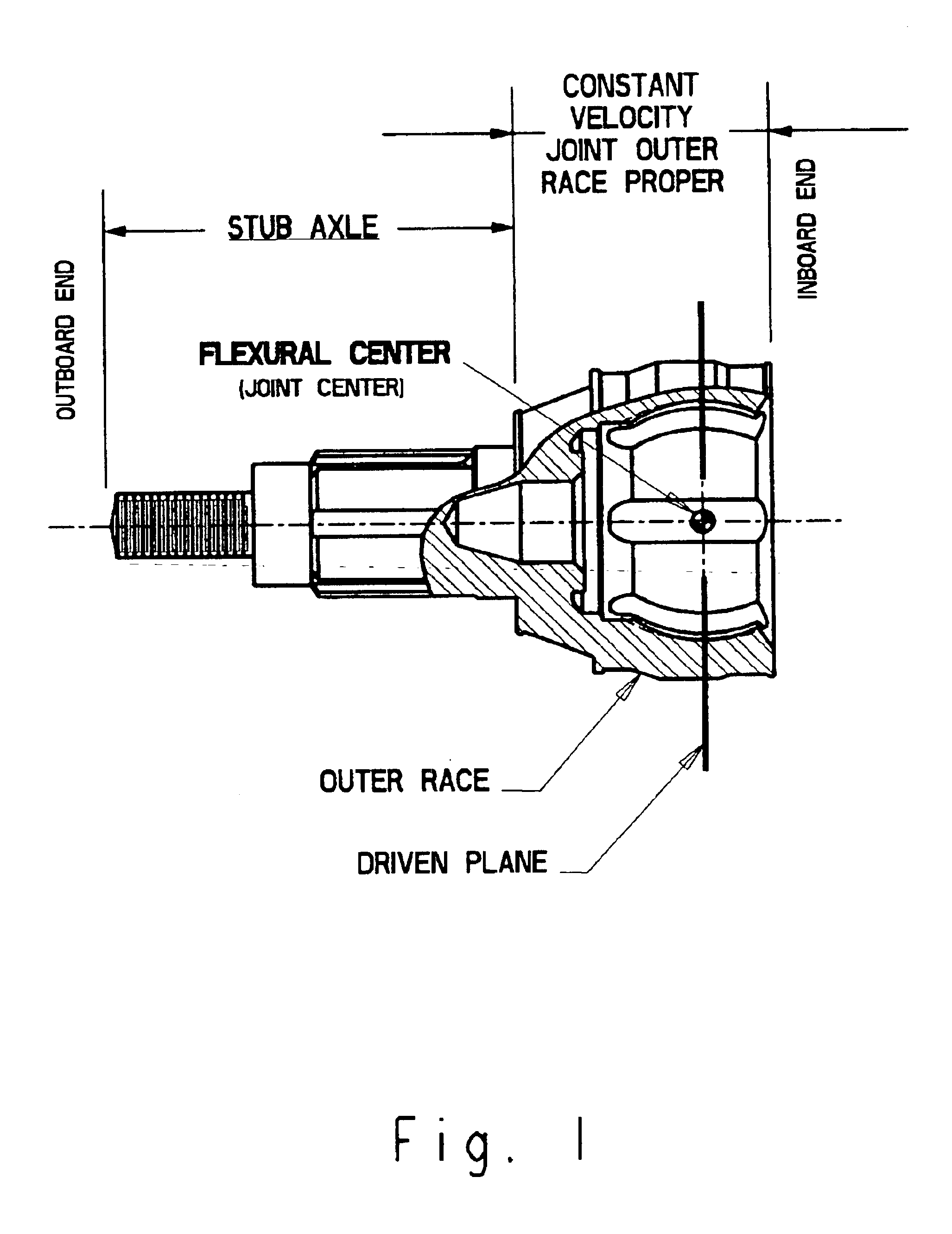
Referring to the drawing in FIG. 2, there is illustrated in side elevation an inboard bearing subassembly which includes a CV joint outer race proper 10 and a concentric laterally outwardly extending stub shaft 13, said outer race is configured to include a conical raceway 11 for being in bearing contact with a plurality of rolling elements 22, said rolling elements being retained thereto by spacer cage 23.

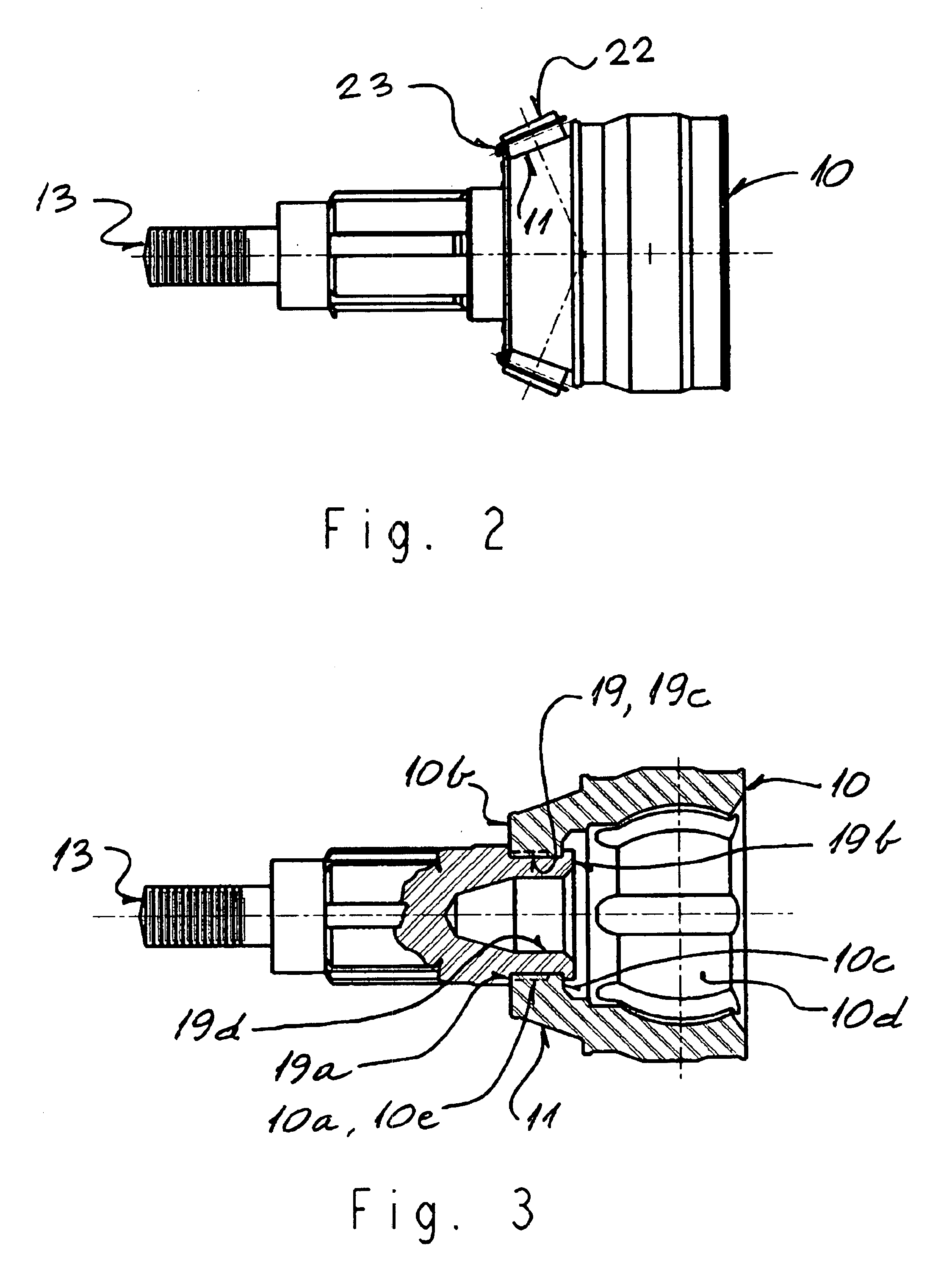
Referring to the drawing in FIG. 3, there is illustrated a side elevation with broken out sectional view a subassembly comprising the CV joint's outer race proper 10 and a concentric mechanically integrated discrete stub axle 13 extending outwardly therefrom.

CV joint's outer race proper 10, made of rolli...


PUM


Abstract

Mounted in a suspension upright for land vehicles, there is provided an arrangement comprising a constant velocity joint, a hub and two wheel bearings with provision for preload adjustment, wherein the CV joint's outer race proper is the inboard wheel bearing's inner race. The bearing raceway formed on the exterior surface of the CV joint's outer race proper is located so as to be in the general area occupied by the driven plane in line with the CV joint's flexural center, providing full end support to the CV joint itself, and concurrently bring about increased axial spacing between the inboard and outboard bearings. Having the CV joint's outer race proper thus integrated to the inboard wheel bearing, a robust hub assembly is provided, wherein the CV joint's flexural center can be placed more closely to the wheel center plane than is normally possible, making negative scrub radius with low kingpin inclination easily achievable.

Description

FIELD OF THE INVENTIONThe present invention relates to improvements in the method of supporting the constant velocity joint outer race proper at the wheel end of an axle-driving shaft in a hub assembly of an independent type suspension layout for a wheeled vehicle and further, discloses more than one method devised for preload adjustment of wheel bearings in such an assembly.In the following description of both the prior art and this invention, the term “constant velocity joint outer race proper” is intended to be limiting to the extent that it shall denote only the generally bell shaped part of the outer race which contains the ball grooves for transmitting driving torque from the inner race of the joint, which inner race is non-rotatably connected to the drive axle shaft. The term “constant velocity joint's outer race proper” shall specifically exclude that section of the outer race that is the stub axle, that axle being a reduced diameter integral appendage to the outer race. Fur...

Claims


Application Information

Patent Timeline
IPC IPC(8): B60B27/00
CPCB60B27/00F16C2240/80F16C35/063F16C35/073F16C19/364F16C19/548F16C33/581F16C2326/02F16D3/223F16D2003/22326
Inventor CSIK, FRANK VICTOR
Owner CSIK FRANK VICTOR
Why Eureka
Try Eureka