Check patentability & draft patents in minutes with Patsnap Eureka AI!

A time difference location method for truncated broadband chirp signal

A chirp signal and time difference positioning technology, which is used in positioning, radio wave measurement systems, instruments, etc., can solve the problem that the time difference of the truncated broadband chirp signal is difficult to match successfully, and achieve the effect of achieving track and low computational complexity.

Active Publication Date: 2022-02-15
THE 724TH RES INST OF CHINA SHIPBUILDING IND
View PDF14 Cites 0 Cited by
  • Summary
  • Abstract
  • Description
  • Claims
  • Application Information

AI Technical Summary

Problems solved by technology

[0007] The present invention is mainly a time-difference positioning technology for truncated broadband chirp signals, and effectively solves the problem of truncated broadband chirp signals by performing full pulse data preprocessing, target sequence search, frequency domain clustering, time difference clustering, and positioning defuzzification key algorithms for positioning targets The time difference is difficult to match successfully, and the fuzzy solution generated by the positioning process is eliminated by using the convergence consistency of the target trajectory corresponding to the time difference

Method used


Image

  • A time difference location method for truncated broadband chirp signal
  • A time difference location method for truncated broadband chirp signal
  • A time difference location method for truncated broadband chirp signal

Examples


specific Embodiment approach

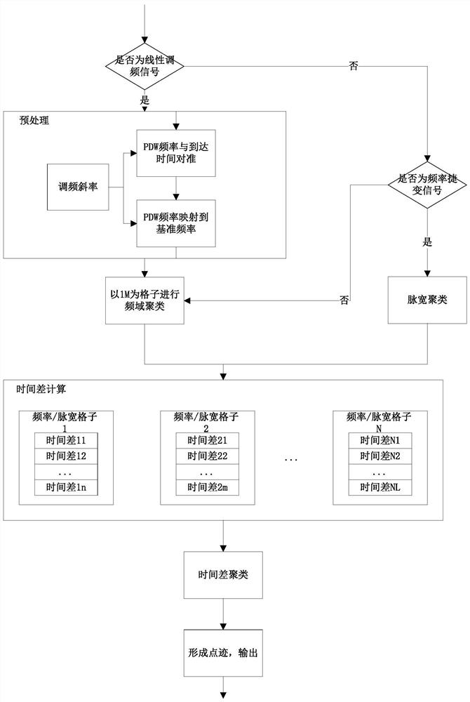
[0014] See the flow chart of the present invention figure 1 , the specific implementation is as follows:

[0015] 1. Preprocessing: such as figure 2 As shown, the preprocessing of the truncated wideband chirp requires two mappings. Convert the full pulse center frequency to the pulse start frequency given the known frequency modulation slope k Select the reference frequency f std Then, convert the pulse arrival time corresponding to the starting frequency to the pulse arrival time corresponding to the reference frequency The three stations respectively convert the truncated broadband chirp signal from frequency domain to time domain, and preprocess the full pulse data.

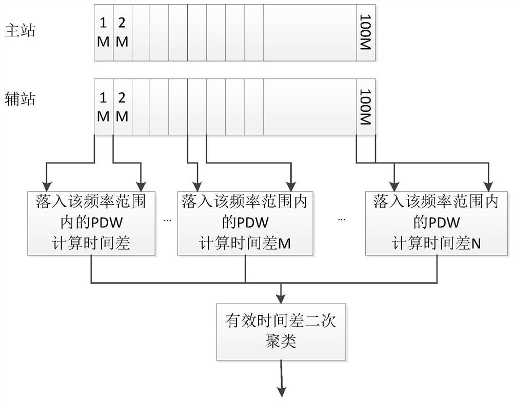
[0016] 2. Frequency domain clustering: Use 1M as the frequency grid to perform frequency domain clustering on all the full pulse data within the bandwidth of the truncated broadband chirp signal. The full pulse data belonging to the same positioning target and with different similarity levels are scree...


PUM


Abstract

The invention relates to a time difference positioning method for truncated broadband chirp signals. The invention can better solve the problem that the wideband chirp signals are difficult to match and locate due to deviations in arrival time difference after the broadband signal is truncated due to channelization. The present invention designs a specific implementation framework mainly based on the main characteristics of the broadband chirp signal and the convergence consistency of the moving target trajectory corresponding to the time difference, and realizes full pulse data preprocessing, target blind positioning (clustering in frequency domain and time domain respectively) and A series of processing such as target association, tracking, filtering, etc. The present invention still has a good positioning effect for the broadband linear frequency modulation signal when it is difficult to completely intercept and the arrival time of the full pulse data deviates.

Description

technical field [0001] The technical invention belongs to the field of passive reconnaissance. Background technique [0002] Time difference positioning is a passive positioning technology that uses the time difference between the arrival of the same radiation source signal to multiple stations to form a hyperbola (surface) for positioning. Long-baseline time difference positioning has been widely used in engineering implementation due to its high positioning accuracy and simple positioning algorithm. However, it has high requirements on the time synchronization between the stations and the accuracy of the arrival time of the target radiation source. [0003] In practical applications, due to the increasingly complex electromagnetic environment and the increasing diversification of radar working systems, the frequency parameters, repetition period parameters, and pulse width parameters of complex radar signals will change. It is difficult for the existing localization mech...

Claims


Application Information

Patent Timeline
Patent Type & Authority Patents(China)
IPC IPC(8): G01S5/02G01S5/06
CPCG01S5/0294G01S5/06
Inventor 朱玉臧勤刘佳媛
Owner THE 724TH RES INST OF CHINA SHIPBUILDING IND
Features
  • R&D
  • Intellectual Property
  • Life Sciences
  • Materials
  • Tech Scout
  • Unparalleled Data Quality
  • Higher Quality Content
  • 60% Fewer Hallucinations
Learn More