

Output parameter adjustment method and adjustment device applied to electronic terminal
An output parameter, electronic terminal technology, applied in the input/output process of data processing, electrical digital data processing, instruments, etc., can solve problems such as easy misoperation, and achieve the effect of convenient use
- Summary
- Abstract
- Description
- Claims
- Application Information
AI Technical Summary
Problems solved by technology
Method used
Image



Examples
Embodiment 1
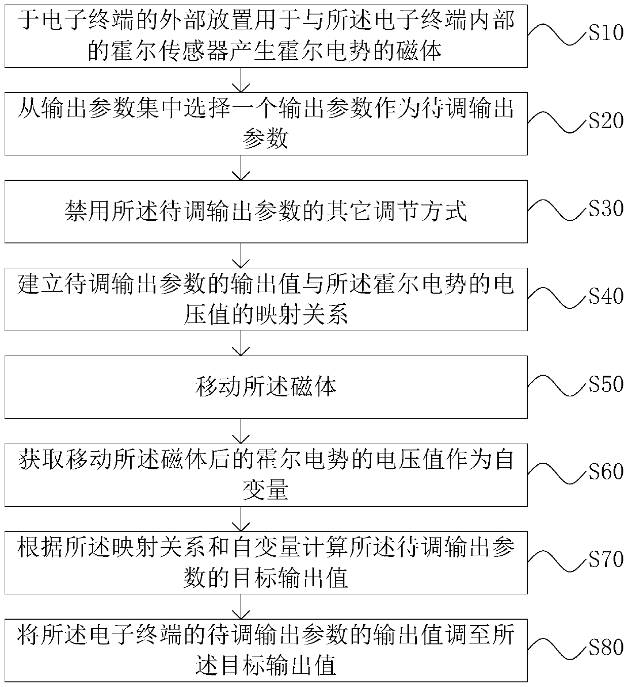
[0068] An embodiment of the present invention provides an output parameter adjustment method applied to an electronic terminal, including:
[0069] S10: Place the magnet 82 for generating a Hall potential with the Hall sensor 100 inside the electronic terminal outside the electronic terminal.
[0070] Specifically, current electronic terminals such as tablet computers, mobile phones, and notebooks are equipped with a Hall sensor 100. The technical solution in the present invention only needs to add a magnet 82 from the outside, so that the magnet 82 and the Hall sensor 100 inside the electronic terminal Matching eliminates the need to add a Hall sensor 100, which not only saves costs, but also provides convenience for users.
[0071] S20: Select an output parameter from the output parameter set as the output parameter to be adjusted.
[0072] Specifically, various output parameters can be adjusted through the adjustment method provided by the present invention. Therefore, bef...
Embodiment 2
[0099] This embodiment provides an adjustment device for adjusting output parameters of an electronic terminal according to the adjustment method in Embodiment 1, which specifically includes a hardware part 80 and a software part.
[0100] The hardware part 80 includes a base 81 and a magnet 82 . Wherein, the base 81 is used for fixed connection with the electronic terminal, and one side of the base 81 is provided with a suction cup or glue, etc., and the base 81 is adhered to the outside of the electronic terminal (located near the Hall sensor 100) through the suction cup or glue, and the base The other side of the 81 is provided with a chute 811; the magnet 82 is located on the side of the base 81 provided with the chute 811, and is slidably connected with the chute 811; the magnet 82 is used to generate a Hall potential with the Hall sensor 100 inside the electronic terminal . Preferably, the sliding direction of the magnet 82 is parallel to the connection surface between ...
PUM
 Abstract
Description
Claims
Application Information