Blasting drilling machine

A technology for drilling machines and drill bits, which is applied to drilling equipment and methods, drilling equipment, and earthwork drilling and mining, and can solve the problems of large size, inconvenient movement, and potential safety hazards of blasting drilling machines, and achieves simple and convenient structure. Effect of moving and stopping, reducing vibration

Inactive Publication Date: 2018-11-30
滕州市凡廷自动化设备有限公司
View PDF0 Cites 3 Cited by
  • Summary
  • Abstract
  • Description
  • Claims
  • Application Information

AI Technical Summary

Problems solved by technology

The existing blasting drilling machine is large in size and inconvenient to move. It vibrates severely during operation. It needs to manually push the motor control process during operation, which has potential safety hazards.

Method used


Image

  • Blasting drilling machine
  • Blasting drilling machine
  • Blasting drilling machine

Examples


Embodiment Construction

[0014] The present invention will be further elaborated below in conjunction with the accompanying drawings and specific embodiments.

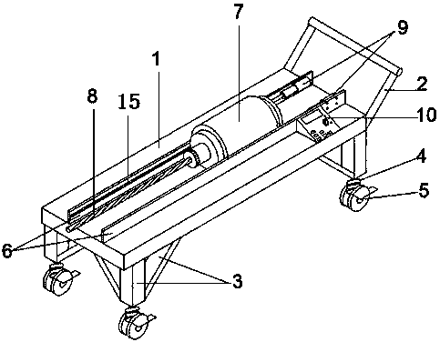
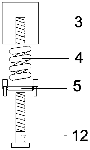
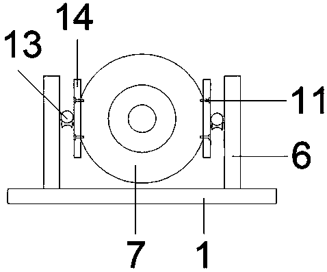
[0015] A blasting drilling machine, comprising a car body 1, a push handle 2, a frame 3, a damping spring 4, wheels 5, a limit plate 6, a slide rail 15, a motor 7, a drill bit 8, a hydraulic rod 9, and a controller 10, The wheels 5 and damping springs 4 are mounted on the bottom of the vehicle frame 3 using screws, and the vehicle frame 3 is welded to the bottom of the vehicle body 1, the push handle 2 is welded to the right side of the vehicle body 1, and the limit plate 6 is welded to the vehicle body 1. The upper surface of the body 1, and the inner side of the right end of the limiting plate 6 is equipped with a hydraulic rod 9, the motor 7 is installed on the inner side of the limiting plate 6 on both sides, and the motor 7 is connected with the hydraulic rod 9, and the drill bit 8 is connected with the motor 7, Described controller 10 is...


PUM


Abstract

The invention relates to a blasting drilling machine which comprises a vehicle body, a pushing handle, a vehicle frame, damping springs, wheels, limiting plates, sliding rails, a motor, a drill bit, hydraulic rods and a controller. The wheels and the damping springs are installed at the bottom of the vehicle frame through screw rods, and the vehicle frame is welded to the bottom of the vehicle body; the pushing handle is welded to the right side of the vehicle body, the limiting plates are welded to the upper surface of the vehicle body, and the hydraulic rods are mounted on the inner sides ofthe right ends of the limiting plates; the motor is installed on the inner sides of the limiting plates on the two sides and connected with the hydraulic rods, and the drill bit is connected with themotor; the controller is installed on the right side of the vehicle body and used for controlling starting and stopping of the motor and the hydraulic rods; and connecting plates are fixed to the twosides of the motor through bolts, and pulleys are fixed to the connecting plates and installed in the sliding rails, and thus the motor slides in the front-back direction along the sliding rails of the limiting plates. The blasting drilling machine is simple in structure, reasonable in design, low in cost, safe, reliable, and suitable for being used and popularized.

Description

technical field [0001] The invention relates to the field of mine production assistance, in particular to a blasting drilling machine. Background technique [0002] In the process of blasting the mountain body, drilling is the first step in blasting, which affects the progress and economic benefits of blasting construction to a great extent. Existing blasting drilling machines are large in size and inconvenient to move. They vibrate severely during operation and need to manually push the motor control process during operation, which poses safety hazards. Contents of the invention [0003] The object of the present invention is to provide a kind of blasting drilling machine, to solve the above technical problems, the present invention adopts the following technical solutions for realizing the above object: [0004] A blasting drilling machine, including car body, push handle, vehicle frame, shock absorbing spring, wheel, limit plate, slide rail, motor, drill bit, hydraulic...

Claims


Application Information

Patent Timeline
IPC IPC(8): E21B7/02F16F15/04
CPCE21B7/027F16F15/04
Inventor 孔凡廷
Owner 滕州市凡廷自动化设备有限公司
Why Eureka
Try Eureka