Intelligent door lock having automatic reset function and high endurance capability
What is Al technical title?
Al technical title is built by PatSnap Al team. It summarizes the technical point description of the patent document.
An automatic reset, smart door lock technology, applied in the field of smart locks, can solve problems such as battery replacement, consumption of light, affecting the use of equipment, etc., to achieve the effect of convenient and reliable operation, enhanced battery life, and reduced power supply time
Active Publication Date: 2018-11-30
浙江金和美工贸有限公司
View PDF14 Cites 1 Cited by
Summary
Abstract
Description
Claims
Application Information
AI Technical Summary
This helps you quickly interpret patents by identifying the three key elements:
Problems solved by technology
Method used
Benefits of technology
Problems solved by technology
[0003] A variety of smart door locks are currently popular in the market, among which fingerprint locks are more widely used. Unlocking through fingerprint recognition is not only convenient and quick, but also safe and reliable. In order to protect the fingerprint window and touch screen on the smart door lock, in the door lock There is usually a slide cover on the phone, but in the actual application process, the user forgets to reset after opening the slide cover, so that the fingerprint window and the touch screen are exposed, and the surface is easy to accumulate dust, which affects the use of the device. Not only that, in the smart door lock , because the dry battery in the door lock continues to supply power to the fingerprint window and the touch screen, the dry battery in the door lock will be exhausted in a short period of time, thereby reducing the battery life of the existing smart door lock. The battery of the lock is replaced, which reduces the practicality of the existing smart door lock
Method used
Image
Click on the blue label to locate the original text in one second.
Reading with bidirectional positioning of images and text.
Examples
Embodiment Construction
[0028] The present invention is described in further detail now in conjunction with accompanying drawing. These drawings are all simplified schematic diagrams, which only illustrate the basic structure of the present invention in a schematic manner, so they only show the configurations related to the present invention.
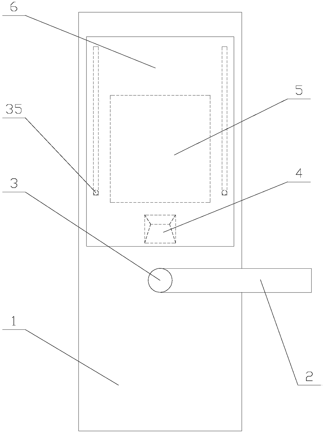
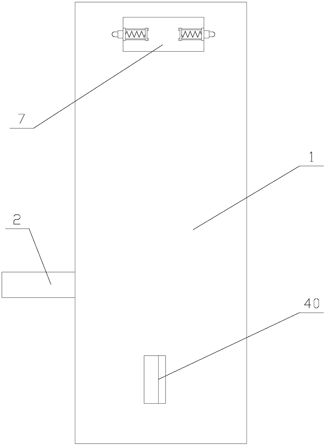
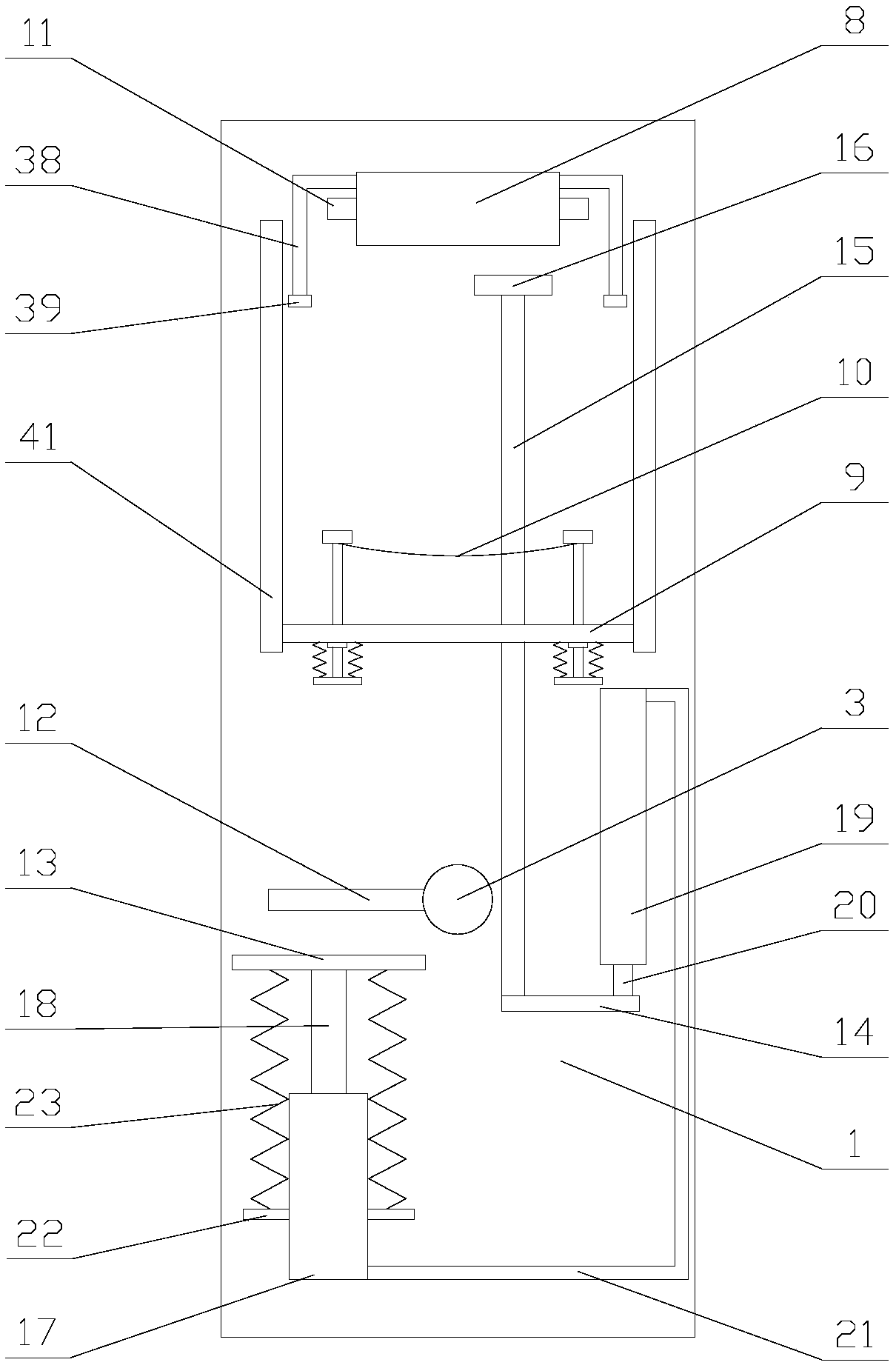
[0029] like Figure 1-2 As shown, a smart door lock with automatic reset function and strong battery life includes a main body 1, and the front of the main body 1 is provided with a handle 2, a rotating shaft 3, a fingerprint window 4, a touch screen 5 and a sliding cover 6. One end of the rotating shaft 3 is fixedly connected with the handle 2, the other end of the rotating shaft 3 is arranged in the main body 1, the touch screen 5 is located above the fingerprint window 4, and two sliding doors are arranged between the sliding cover 6 and the main body 1. Components, the back of the main body 1 is provided with a battery cover 7 and two closure components, ...
PUM
Abstract
The invention relates to an intelligent door lock having an automatic reset function and high endurance capability. The intelligent door lock comprises: a handle, a fingerprint window, a touch screenand a sliding cover are arranged on the front face of a main body, a battery box, a cross bar, a trigger component, two conductive blocks and two conductive components are arranged in the main body, the trigger component comprises a convex rod, a trigger plate, a trigger unit, a moving plate, a vertical rod and a convex plate, and the trigger unit comprises a first cylinder, a first piston, a second cylinder, a second piston, a gas pipe and two reset units. According to the intelligent door lock having the automatic reset function and high endurance capability, the sliding cover is moved upward, so that the conductive components are in contact with the conductive blocks, a dry battery in the battery box supplies power to the touch screen and the fingerprint window, thereby shortening the power supply time and improving the endurance capability of the device. Furthermore, after the handle is rotated, the convex rod causes the convex plate to drive the moving plate to move downward through the trigger component, and then the sliding cover automatically resets via a sliding component to protect the touch screen and the fingerprint window, so that the practicability of the device is improved.
Description
technical field [0001] The invention relates to the field of intelligent locks, in particular to an intelligent door lock with an automatic reset function and strong battery life. Background technique [0002] Smart door lock refers to a lock that is improved on the basis of being different from traditional mechanical locks, and is more intelligent and convenient in terms of user security, identification, and management. The smart door lock is the executive component for locking the door in the access control system. [0003] A variety of smart door locks are currently popular in the market, among which fingerprint locks are more widely used. Unlocking through fingerprint recognition is not only convenient and quick, but also safe and reliable. In order to protect the fingerprint window and touch screen on the smart door lock, in the door lock There is usually a slide cover on the phone, but in the actual application process, the user forgets to reset after opening the slid...
Claims
Application Information
Patent Timeline
Application Date:The date an application was filed.
Publication Date:The date a patent or application was officially published.
First Publication Date:The earliest publication date of a patent with the same application number.
Issue Date:Publication date of the patent grant document.
PCT Entry Date:The Entry date of PCT National Phase.
Estimated Expiry Date:The statutory expiry date of a patent right according to the Patent Law, and it is the longest term of protection that the patent right can achieve without the termination of the patent right due to other reasons(Term extension factor has been taken into account ).
Invalid Date:Actual expiry date is based on effective date or publication date of legal transaction data of invalid patent.