Safe and stable intelligent door lock adopting two power supplies and having switching function

A safe, stable, switching function technology, applied in the field of smart locks, can solve the problems of weakening the battery life of the device, reducing the practicability of the smart lock, shortening the service life of the power supply, etc., to achieve the effect of strengthening the battery life, improving the practicability, and reducing the power supply time.

Active Publication Date: 2018-12-14
温州品力智能幕墙门窗有限公司
View PDF6 Cites 0 Cited by
  • Summary
  • Abstract
  • Description
  • Claims
  • Application Information

AI Technical Summary

Problems solved by technology

[0003] Inside the existing smart door lock, a single power supply is usually used to supply power to the locked touch screen and fingerprint window. When the power in the power supply is exhausted, if the owner fails to replace the battery in time, the owner is easily locked out of the door. Unable to open the door to enter the room, not only that, because the touch screen and fingerprint window in the door lock are always powered on, so that the device has been consuming power in the power supply, which in turn shortens the service life of the power supply and weakens the battery life of the device capability, thereby reducing the practicality of existing smart locks

Method used


Image

  • Safe and stable intelligent door lock adopting two power supplies and having switching function
  • Safe and stable intelligent door lock adopting two power supplies and having switching function
  • Safe and stable intelligent door lock adopting two power supplies and having switching function

Examples


Embodiment Construction

[0028] The present invention is described in further detail now in conjunction with accompanying drawing. These drawings are all simplified schematic diagrams, which only illustrate the basic structure of the present invention in a schematic manner, so they only show the configurations related to the present invention.

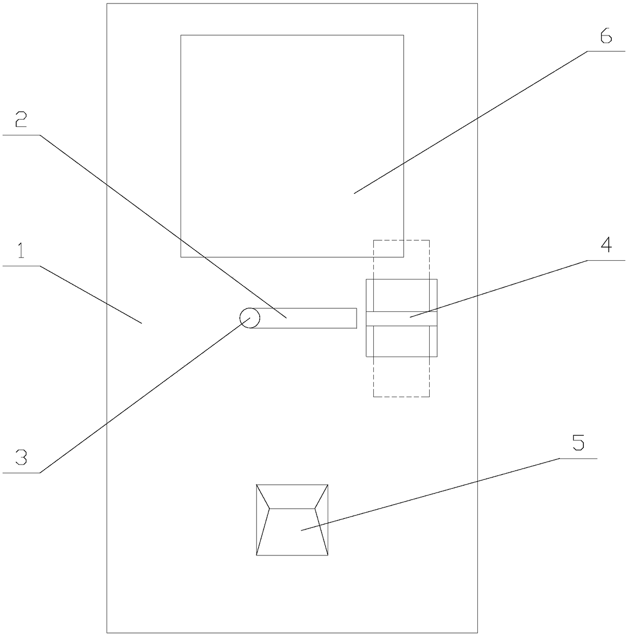
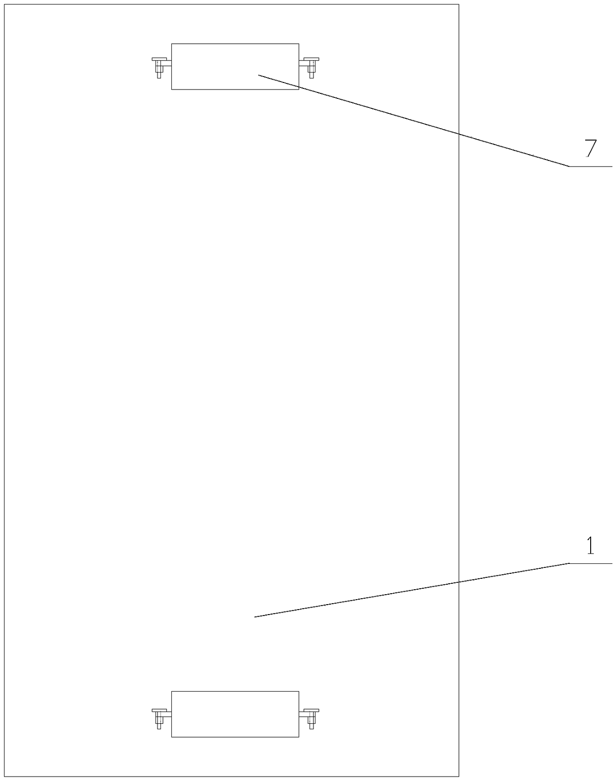
[0029] Such as Figure 1-2 As shown, a safe and stable intelligent door lock with switching function and adopting dual power supplies includes a main body 1, and the front of the main body 1 is provided with a handle 2, a rotating shaft 3, an opening, a card plate 4, a fingerprint window 5 and a touch screen 6. One end of the handle 2 is fixed on the rotating shaft 3, the other end of the rotating shaft 3 is set in the main body 1, the opening is set on the main body 1, the clamping plate 4 is set at the opening, the main body The back of 1 is provided with two battery covers 7, and the two ends of the battery covers 7 are provided with installation component...


PUM


Abstract

The invention relates to a safe and stable intelligent door lock adopting two power supplies and having a switching function. The safe and stable intelligent door lock comprises a main body; a handle,a rotating shaft, a clamping plate, a fingerprint window and a touch screen are arranged on the front surface of the main body; a gear, a movable plate, a movement mechanism and two power supply mechanisms are arranged in the main body; each power supply mechanism comprises a battery box, a translation plate, a connecting assembly, two electric conducting rods and two electric conduction assemblies; and the movement mechanism comprises a frame, a movable plate, two sliding plates and two fixing assemblies. When the safe and stable intelligent door lock adopting the dual power supply and having the switching function is in use, any one power supply mechanism can be selected by the clamping plate via the movement mechanism to supply power to a touch screen and a fingerprint window, so thatsufficient energy is provided when equipment is required to be used, an owner is prevented from being locked in a room, and the operation is more convenient. In addition, after the handle is rotated,power supply assemblies can automatically cut off the power of the touch screen and the fingerprint window, so that the power-on time is shortened, the cruising power is strengthened, and the practicability of the equipment is improved.

Description

technical field [0001] The invention relates to the field of intelligent locks, in particular to a safe and stable intelligent door lock with switching function and adopting dual power supplies. Background technique [0002] Smart door lock refers to a lock that is improved on the basis of being different from traditional mechanical locks, and is more intelligent and convenient in terms of user security, identification, and management. The smart door lock is the executive component for locking the door in the access control system. [0003] Inside the existing smart door lock, a single power supply is usually used to supply power to the locked touch screen and fingerprint window. When the power in the power supply is exhausted, if the owner fails to replace the battery in time, the owner is easily locked out of the door. Unable to open the door to enter the room, not only that, because the touch screen and fingerprint window in the door lock are always powered on, so that t...

Claims


Application Information

Patent Timeline
Patent Type & Authority Applications(China)
IPC IPC(8): E05B47/00E05B17/00
CPCE05B17/00E05B47/00E05B2047/0053E05B2047/0058
Inventor 蒙泽喜
Owner 温州品力智能幕墙门窗有限公司
Why Eureka
Try Eureka